Collins 75S-1 — Serial Number & Production Guide
VK6ADA Technical Reference · Collins S-Line Vintage Amateur Equipment · March 2026 · Mike Peace VK6ADA
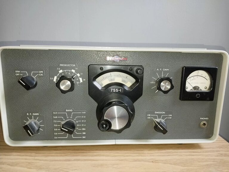
The Collins 75S-1 SSB Receiver was the first of the S-Line receiver series, introduced in 1959 alongside the companion 32S-1 transmitter.[1] Produced at the Cedar Rapids, Iowa facility through approximately 1962–1963, the 75S-1 established the benchmark for amateur HF SSB reception using Collins Mechanical Filter technology. This guide consolidates serial number ranges, emblem transitions, manual edition history, and known circuit variations to assist collectors and restorers in authenticating and dating their units.
Overview & Specifications
Manufacturer | Collins Radio Company — Cedar Rapids Division, Cedar Rapids, Iowa |
Model Number | 75S-1 (Collins type designation: SSB/CW Receiver) |
Production Period | ~1959 – approximately 1962–1963 |
Receiver Type | Double-conversion superheterodyne with Collins Mechanical Filters |
Frequency Coverage | 3.4 – 30.0 MHz (amateur bands: 80, 40, 20, 15, 10 m) |
IF Frequency | First IF: 3.395 MHz (Crystal filter); Second IF: 455 kHz (Mechanical Filter selectivity) |
Crystal Filter | Collins Mechanical Filters — standard: 500 Hz (CW) and 3.1 kHz (SSB) |
Optional Filter | 2.1 kHz Mechanical Filter (Bandwidth selector on front panel) |
Modes | USB, LSB, CW, AM (envelope detector) |
Sensitivity (SSB/CW) | ≤ 0.5 µV for 10 dB S+N/N |
Mains Supply | 115 V AC or 230 V AC, 60 Hz single-phase (primary wiring selectable) |
Companion Transmitter | Collins 32S-1 |
Companion Amplifier | Collins 30L-1 Linear Amplifier |
Introduced | ~1959 [10] |
Important Note on Serial Number Sequencing
Per CCA historical research and a direct account from a former Collins employee,[9] Art Collins decreed that S-Line serial numbers were to be issued in random (non-sequential) order to prevent price discrimination among model variants sharing the same chassis. A lower serial number does not necessarily indicate an earlier production date. Broad ranges, cross-referenced with emblem type and internal component date codes, are the most reliable dating approach.
Collins Logo / Emblem Production Eras
The 75S-1 production ended approximately 1962–1963, well before the Collins emblem transition in Fall 1969. As a result, all authentic 75S-1 units should carry the Winged Emblem. Any 75S-1 presented with a Round Emblem requires careful authentication.[3]
| Emblem Type | Production Period | 75S-1 Applicability | Physical Description |
|---|---|---|---|
| Winged Emblem | 1959 – Fall 1969 [3] | Standard / expected on all authentic 75S-1 units. | Classic silver-and-blue winged Collins insignia. Two mounting holes visible either side if badge was ever replaced. |
| Round Emblem Transition | Fall 1969 only [3] | Not applicable — production ended ~6 years before emblem change. | Round “meatball” emblem plus grey screws in former wing holes. |
| Small Round Emblem | Fall 1969 – ~1975 [3] | Not applicable. | Circular emblem (~18 mm diam.). |
| Large Round Emblem | ~1974 – FY1976 [3] | Not applicable. | Round emblem (~21 mm diam.). |
Serial Number Lookup Reference
Quick Era Identifier — Enter Your Serial Number
Documented Serial Number Data Points
| Serial Number | Emblem / Era | Notable Features | Source / Reference |
|---|---|---|---|
| ~1xx – ~1,xxx range | Winged | Earliest 75S-1 production; consistent with 1959–1960. 500 Hz and 3.1 kHz mechanical filters standard. Original tube complement typically intact in unrestored examples. | CCA S-Line survey data [4] |
| ~3,xxx – 5,xxx range | Winged | Mid production; consistent with 1960–1962. Component date codes in this range typically confirm early 1960s manufacture. | CCA survey / collector community [4] |
| ~5,xxx – 7,xxx range | Winged | Final production years. Cross-reference carefully with model designation — late 75S-1 serials may approach the overlap zone with 75S-2 numbering. | QRZ Forums / community documentation [7] |
Manual Edition History
| Edition | Date | Notes |
|---|---|---|
| 1st Edition | ~1959 | Original publication with initial 75S-1 production. Archived at Collins Radio Association (CRA).[1] |
| ~2nd–4th Editions | 1960–1963 | Progressive service bulletin amendments. Available via CRA archive and worldradiohistory.com. |
Circuit Notes & Filter Variants
The 75S-1’s primary differentiation from later S-Line receivers lies in its mechanical filter complement. Understanding what filters are fitted, and whether they are original or field-modified, is essential to assessing a 75S-1’s operating condition and value.
| Filter / Feature | 75S-1 Standard Fit | Notes |
|---|---|---|
| CW Filter | 500 Hz Collins Mechanical Filter (F455-HC-1 or equivalent) | Standard fit. Provides exceptional CW selectivity. Seldom fails — confirm function with signal generator. |
| SSB Filter | 3.1 kHz Collins Mechanical Filter | Standard fit. Primary SSB reception filter. Check for any wideband distortion suggesting a shorted or cracked element. |
| Optional 2.1 kHz Filter | Optional factory fit or field-installed | Some 75S-1 units were shipped with a 2.1 kHz filter fitted; others were retrofitted in the field. Confirm against the wiring shown in the applicable instruction book edition. |
| AGC System | Standard hang AGC | Service bulletins addressed AGC stability. Check applicable bulletin numbers in the instruction book for any factory-issued corrections. |
| BFO | Built-in crystal BFO | Provides USB, LSB, and CW beat-note injection. Verify BFO crystal is original and within calibration. |
Physical Identification Guide
Step 1 — Front Panel Emblem
All authentic 75S-1 units carry the Winged Emblem. This is the definitive visual identifier distinguishing the 75S-1 from the Round Emblem-era 75S-3 at a distance.
Step 2 — Model Designation
Verify “75S-1” on the front panel label and rear serial number plate. The 75S-1, 75S-2, and 75S-3 share a similar front-panel layout. The key visual differences between 75S-1 and 75S-3 include the filter selection switch positions and front-panel labelling for available filter bandwidths.
Step 3 — Serial Number and Component Date Codes
Rear panel serial number plate — plain integer. Cross-reference with estimates above. Internal electrolytic capacitors carry YY WW date codes; latest original date code establishes earliest ship date. For a 75S-1, expect date codes in the 1959–1963 window.
Step 4 — Manual Edition Check
Original 75S-1 instruction books show copyright dates of 1959–1963 only. A manual with copyright dates extending beyond 1965 is a 75S-2 or 75S-3 manual and should not be used as a 75S-1 service reference.
Typical Restoration Considerations
| Component | Recommended Action | Notes |
|---|---|---|
| Electrolytic Capacitors | Reform or replace — first priority | 60+ years old. Complete capacitor replacement is recommended for any unit that has been in long-term storage. |
| Power Supply Rectifiers | Replace with modern silicon equivalents | Original selenium rectifiers must be replaced. 1N4007 or equivalent is standard replacement. |
| Tube Complement | Test all tubes; prioritise RF and IF stages | Original 6BA6, 6BE6, 6AW8, and associated tube types. Test with accurate tube tester; replace weak examples with matched types. |
| Mechanical Filters | Test insertion loss; seldom require replacement | Collins mechanical filters are highly reliable. Replacement only on confirmed failure verified with signal generator. |
| BFO Calibration | Verify USB/LSB/CW beat frequencies | BFO crystal frequency should be verified against known-good standard. Re-seal if any frequency drift observed. |
| PTO (VFO) | Verify alignment and drift | The permeability-tuned oscillator is precision Collins engineering. Evaluate drift only after 30+ minute warm-up. Do not adjust if within specification. |
This guide consolidates publicly available CCA survey data, community restoration reports, and documented sale records. Serial number range estimates should be treated as approximations. Contributions and corrections welcome via vk6ada.com.au or r-390a.net.
References, Citations & Credits
- Collins Radio Company. 75S-1 Receiver Instruction Book. Cedar Rapids Division, Cedar Rapids, Iowa. Various editions ~1959–1963. Archived by the CRA: collinsradio.org — Technical Archives
- Collins Radio Company. 75S-1 Receiver Instruction Book, final edition. CRA archive: collinsradio.org
- Blocksome, Rod K0DAS. “The Collins S-Line Logo and Emblem Transition History.” CCA Historical Archives. 2013–2016. collinsradio.org — Historical Archives
- Blocksome, Rod K0DAS. Collins S-Line Receiver Production Surveys. CCA Technical Archives. Various years. collinsradio.org — Blocksome Surveys
- Collins Radio Association. Collins Radio Technical Archives. collinsradio.org
- WA3KEY Virtual Collins Radio Museum. Collins 75S-1 Reference Pages. wa3key.com. Accessed 2026.
- QRZ Forums — multiple threads documenting Collins 75S-1 serial numbers, restoration notes, and filter configurations. forums.qrz.com. Accessed 2026.
- Collins Collectors Association FAQ. Biographical notes on Collins Radio engineers, including Dennis Day (75S-3 series). WA3KEY: wa3key.com/ccafaq.html. Accessed 2026.
- Anonymous (attributed to a former Collins employee; reported by Roger KB4THL). “[Collins] Winged versus Round Emblems.” QTH.net Collins Reflector, July 2005. qth.net — July 2005
- QST Magazine — Collins Radio advertisement, 75S-1 Receiver, ARRL, 1959. QST archive: worldradiohistory.com
- Peace, Mike VK6ADA (Administrator). r-390a.net. r-390a.net.
- Peace, Mike VK6ADA. Collins 75S-1 Receiver Project — vk6ada.com.au. vk6ada.com.au/collins-75s-1-receiver/. 2025–2026.