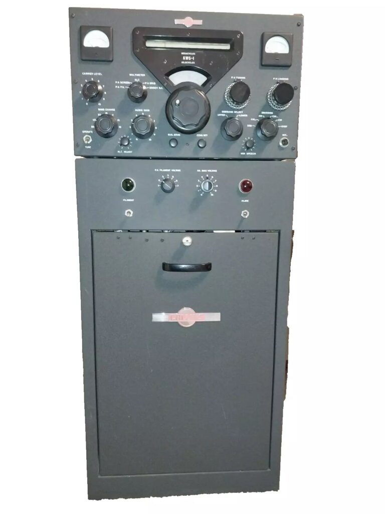
Collins KWS-1 Kilowatt Sideband Transmitter
Failure Prevention Kit — Component & Modification Design
A complete engineering analysis of the ten predictable KWS-1 failure modes: HV power supply electrolytic capacitors at ~2000–2500 V DC, PA final tube ageing and screen current runaway, low-voltage supply capacitors, paper and wax capacitor replacement throughout the exciter chain, carbon composition resistor drift in the ALC and bias circuits, Collins mechanical filter failure in the SSB generation path, screen supply regulation collapse, bandswitch contact arcing under RF load, ALC system component ageing, and driver and exciter tube ageing. Covers all production versions c. 1955–1964 and all service bulletin revisions.
The Collins KWS-1 (Kilowatt Sideband, c. 1955–1964) was Collins’ flagship amateur transmitter and one of the most significant pieces of equipment in the history of amateur SSB. At a time when kilowatt-class SSB was a professional rarity, the KWS-1 brought it to the amateur station. It uses the Collins filter method — a balanced modulator producing a double-sideband suppressed-carrier signal, followed by a Collins mechanical filter at 455 kc that removes the unwanted sideband and residual carrier — to generate SSB of a quality that established the standard against which all subsequent commercial amateur SSB equipment was measured.
The KWS-1 is architecturally distinct from every other item in this failure prevention series. It is a transmitter, not a receiver: it deals with generated RF power, not received signals. The consequences of component failure scale accordingly. A failed capacitor in a receiver degrades sensitivity; a failed capacitor in the KWS-1 HV supply stores enough energy to kill instantly. A screen voltage regulator failure that causes screen current runaway will destroy the PA final tubes within seconds. The restoration and maintenance approach reflects this difference throughout.
After 60–70 years, every electrolytic and paper capacitor in the KWS-1 requires replacement without exception. The HV supply capacitors must be treated as a lethal hazard even after switch-off. The PA final tubes must be tested, conditioned, and monitored for screen current before full-power operation. The Collins mechanical filter in the SSB generation path must be inspected for transducer lead fracture. The ALC system components must be measured for drift. This guide documents all ten predictable failure modes and the restoration procedure required to address each one.
Section 1 — Transmitter Overview
Design Generation and Historical Significance
The KWS-1 arrived at the moment Collins was defining SSB as the future of amateur HF communication. The receiver side of the station was the 75A-3 (and later 75A-4); the KWS-1 was the transmitter that completed it. Where earlier amateur transmitters had treated SSB as an accessory mode added to an AM-based design, the KWS-1 was designed from the outset as an SSB machine. Its filter-method SSB generation produced carrier and opposite-sideband suppression specifications that the community had not previously seen in amateur equipment.
The transmitter is a high-power linear amplifier chain. The exciter section generates a low-power SSB signal at 455 kc using a balanced modulator and Collins mechanical filter; this signal is then heterodyned to the operating frequency, amplified through a driver stage, and finally presented to the high-power PA final stage. The PA operates in Class AB1 or AB2 (depending on operating mode) to preserve the linearity required for SSB. A wideband ALC (Automatic Level Control) system senses output power and adjusts drive level to prevent flat-topping and maintain consistent carrier envelope on voice peaks.
Production Versions
The KWS-1 was produced from approximately 1955 to 1964. Production changes over this span are documented through Collins service bulletins held in the CCA archive at collinsradio.org. Cosmetic and circuit revisions exist across the production run; the service manual edition applicable to a specific unit is identified by serial number. All restoration procedures in this guide apply across all production versions; verify specific component values (particularly HV filter capacitor ratings and screen supply resistor values) from the correct service manual edition before ordering parts.
Tube Complement
Section 2 — The Ten Predictable Failure Modes
The failure modes are ordered from the most immediately lethal to the most operationally degrading. Failure modes F-01 through F-07 are Tier 1: they must be addressed before any powered operation. F-01 (HV supply) is the absolute first priority; work on any other section of the chassis must not begin until the HV capacitor safety condition has been verified. Failure modes F-08 through F-10 are Tier 2.
-
F-01
HV power supply electrolytic capacitors — IMMEDIATELY LETHAL TIER 1 — ABSOLUTE FIRST PRIORITY The KWS-1 main HV supply operates at approximately 2000–2500 V DC, derived from a conventional full-wave rectifier feeding a multi-section capacitor filter bank. The filter capacitors store a charge that is fatal at any human body impedance encountered in normal workshop conditions. Three concurrent failure risks:
(a) Capacitor dielectric failure. After 60–70 years, aluminium electrolytic capacitors at this voltage rating have exceeded their design life. Internal dielectric breakdown causes catastrophic failure: the capacitor vents electrolyte, arcs internally, or fails open. An open HV filter capacitor increases B+ ripple and HV regulation failure, producing 100–120 Hz modulation across all transmitted audio. A shorted HV capacitor causes the HV transformer to fail immediately. Replace all HV filter capacitors before any powered operation, regardless of apparent visual condition.
(b) Bleeder resistor failure. The bleeder resistor chain across the HV filter capacitors discharges the supply to a safe level after power-off. Carbon composition bleeder resistors drift open-circuit with age — a resistor measuring 47 kΩ on the shelf may be several megohms when hot inside the chassis. A unit with open bleeders retains lethal charge indefinitely after switch-off. Verify bleeder continuity out-of-circuit before any other work. Replace any bleeder resistor that measures more than 10% above its nominal value with a wirewound or metal oxide type of the same nominal value and at least double the original wattage rating.
(c) Voltage rating margin. The original HV capacitors were specified at the nominal operating voltage. Replace with capacitors rated at a minimum of 1.5× the measured HV standing voltage (no-load); for a 2500 V supply, use capacitors rated at 3500 V or greater. Modern Cornell Dubilier, Illinois Capacitor, or F&T high-voltage electrolytics are appropriate. Do not use axial electrolytics repurposed from low-voltage applications. -
F-02
PA final amplifier tube ageing and screen current runaway TIER 1 — DESTRUCTIVE IF UNCONTROLLED The PA final tubes are the highest-stress components in the KWS-1. They operate at maximum rated plate voltage and dissipation during normal SSB voice operation. Two failure mechanisms must be understood:
(a) Emission degradation (gradual). Thermionic emission from the PA cathode decreases over thousands of hours of plate-on operation. The primary indication is reduced maximum output power despite correct drive level, requiring increasing drive to achieve rated output. As emission falls, the driver stage is asked to overdrive its own linearity range. An emission-depleted PA tube set degrades output spectral purity before it degrades output power measurably. Test the PA tube set on a calibrated tube tester or by measuring plate and screen currents at a fixed operating point; compare against service manual specifications. Replace the PA tubes as a matched pair when either tube falls below 80% of rated emission.
(b) Screen current runaway (sudden and destructive). In a tetrode PA operating at high plate voltage, if the screen voltage rises above its operating point — due to screen supply regulator failure (see Failure Mode F-07), screen bypass capacitor failure, or a tube developing excessive screen emission — screen current increases, which raises screen dissipation, which raises screen temperature, which further increases screen emission: a thermal runaway cycle that destroys the PA tube in seconds. A screen current meter is mandatory for safe KWS-1 operation. Monitor screen current continuously during any tune-up or full-power operation. If screen current rises above the service manual limit at any point, switch off the HV immediately. Do not operate without functional screen current indication. -
F-03
Low-voltage supply electrolytic capacitors TIER 1 — MANDATORY The KWS-1 low-voltage supply (~300 V B+) powers the exciter chain, driver stage screens, speech amplifier, ALC circuits, and control functions. The LV filter capacitors share the same age-related failure profile as those in the 75A-series receivers: capacitance loss, elevated ESR, and moisture ingress. Failure symptoms: audible 120 Hz hum in the transmitted audio (main LV filter), motorboating or spurious oscillation in the exciter stages (screen bypass capacitor failure), or ALC instability (ALC supply bypass failure). Replace all LV electrolytics as a single kit, working from the service manual parts list. Use 105°C rated modern types throughout. Verify LV under load against service manual specification after replacement and before proceeding to HV work.
-
F-04
Paper and wax capacitor replacement — full exciter and power supply chain TIER 1 — MANDATORY The KWS-1 exciter, speech amplifier, ALC, control, and power supply sections contain approximately 25–35 paper and wax-impregnated tubular capacitors. These fail as leaky (partial DC conduction through the dielectric) or short-circuit (complete failure). In a receiver, a leaky capacitor degrades sensitivity; in the KWS-1 exciter chain, a leaky capacitor causes incorrect tube bias that degrades SSB linearity and carrier suppression — the transmitter will appear to work but its spectral output will fail any modern emissions standard. Replace all paper/wax capacitors with modern polypropylene or polyester film types of equal or greater voltage rating. Pay particular attention to coupling and bypass capacitors in the balanced modulator circuit (V balanced modulator pair) — any asymmetry introduced by a leaky coupling capacitor directly degrades carrier null depth.
-
F-05
Carbon composition resistor drift — ALC threshold, bias, and exciter sections TIER 1 — MEASURE BEFORE ALIGNMENT Carbon composition resistors in the ALC threshold-setting network, the PA grid bias supply, and the balanced modulator bias circuits drift upward in value after 60–70 years of operation at elevated chassis temperatures. In a receiver, drifted IF bias resistors degrade selectivity; in the KWS-1, drifted ALC resistors shift the output power threshold, causing the transmitter to either run above rated power (ALC threshold too high — spectral splatter, potential PA damage) or over-compress at low power levels (ALC threshold too low — low output, flat audio). Drifted balanced modulator bias resistors raise the residual carrier level in the transmitted SSB signal. Procedure: measure all carbon composition resistors in the ALC, balanced modulator, and PA grid bias sections out-of-circuit. Replace any reading more than 5% above or below nominal with 1% metal film resistors. This work must be completed before any transmit testing or ALC alignment.
-
F-06
Collins mechanical filter — SSB generation path TIER 1 — NOT FIELD REPAIRABLE The KWS-1 SSB generation chain uses a Collins mechanical filter at 455 kc to select the desired sideband and suppress the carrier and opposite sideband. The transmit mechanical filter is subject to the same failure modes as the receive filter documented for the 75A-4: (a) transducer lead solder joint fracture, causing loss of filter throughput (transmitter produces no output, or severely degraded carrier/sideband suppression); and (b) long-term insertion loss increase, raising the drive level required to achieve rated output. A failed transmit mechanical filter has far more visible regulatory consequences than a failed receive filter: reduced sideband suppression produces spectral emissions that violate Part 97 amateur spectral purity requirements. Inspect the transducer lead solder joints under magnification before any other work. Measure insertion loss at 455 kc (service manual specification). Handle with the same physical shock precautions as the 75A-4 receive filter — the filter cannot be dropped, jarred, or subjected to ultrasonic cleaning. NOS Collins transmit mechanical filters are available in some specialist markets but increasingly scarce; their scarcity justifies treating the installed unit as irreplaceable. Do not test the filter by applying full transmit drive without first verifying filter integrity.
-
F-07
Screen supply voltage regulation — PA protection critical path TIER 1 — PA TUBE PROTECTION The PA final tetrode screen voltage is regulated by a dedicated regulation circuit. Unlike the plate supply (which is set by transformer design and rectifier output), the screen supply is actively controlled. Regulation component failures fall into two categories:
(a) Regulation collapse (screen voltage rises). If the screen voltage regulator tube or its associated bypass and filtering components fail open, the screen voltage rises to an unregulated level. This immediately initiates the screen current runaway cycle described in Failure Mode F-02, destroying the PA tubes within seconds of transmit switching. The screen supply bypass electrolytic (which must be replaced as part of the mandatory cap kit) is the most common cause of regulation instability in aged units.
(b) Regulation collapse (screen voltage falls). If the regulator fails in the low-voltage direction, the PA tubes are under-screened: output power falls and the driver is loaded into an abnormal impedance. This failure mode is less immediately destructive than (a) but produces abnormal screen and plate current readings that serve as diagnostic indicators.
After completing the electrolytic cap replacement kit (F-01, F-03), verify screen voltage at the PA screen terminal against the service manual specification before any transmit testing. If screen voltage is outside the specified range after cap replacement, inspect the screen regulator circuit components before applying HV. -
F-08
Bandswitch contacts and tank circuit integrity under RF load TIER 2 The KWS-1 output bandswitch routes high-power RF through silver-plated wafer contacts at power levels up to 1 kW PEP. At these power levels, oxidised or pitted contact surfaces develop resistive heating that accelerates contact damage, increasing contact resistance further. The failure signature is band-specific output power reduction: one or two bands produce significantly lower output than adjacent bands with identical drive and loading, without any change in PA plate or screen current. Secondary risk: the tank circuit variable capacitors and coil assembly are subject to RF arcing if the air gap between capacitor plates is reduced by foreign material (dust compaction, corrosion particles) or if the capacitor frame develops play that reduces the minimum plate gap under vibration. Service: apply DeOxit D5 to all bandswitch wafer contacts; cycle through all bands 20–30 times. Remove any foreign material from variable capacitor plates using clean, dry compressed air — never introduce moisture or solvents to the tank capacitors. Inspect all tank circuit solder connections for thermal stress fractures.
-
F-09
ALC system component ageing — linearity loss and over-compression TIER 2 The Automatic Level Control system monitors transmitted output power and reduces drive level to prevent envelope flat-topping on voice peaks. The ALC loop contains: an RF sampling circuit, a detector diode (6AL5 or equivalent), an ALC amplifier and integrator (time constant capacitors and resistors), and a control voltage path back to the speech amplifier gain stage. Three component ageing effects degrade ALC performance:
(a) Time constant capacitor drift. The ALC attack and decay time constant capacitors (wax/paper or electrolytic types) lose capacitance, shortening the decay time. A fast ALC decay causes “pumping” of the audio between syllables, audible as rapid gain variation. Replace all ALC time constant capacitors with modern film types (NP0 for small values, polypropylene for larger) — addressed as part of the F-04 paper cap replacement.
(b) ALC threshold resistor drift. The voltage-divider network setting the ALC engagement threshold shifts as carbon comp resistors drift high. The result: the ALC engages at a lower output power level than designed, producing excessive compression and “processed”-sounding audio — or at too high a level, allowing flat-topping to occur before ALC acts. Addressed as part of F-05 resistor audit.
(c) ALC detector diode ageing. The 6AL5 (or equivalent) detector tube that samples the RF envelope loses forward transconductance with age, reducing ALC sensitivity. Replace the ALC detector tube with a known-good NOS type during the tube complement replacement. -
F-10
Driver tube, HV rectifier, and exciter chain tube ageing TIER 2 Driver (6146/6146B): the driver must provide linear RF drive to the PA input across all bands. Emission degradation in the driver tube causes reduced available drive power, forcing the PA into abnormal loading conditions and reducing maximum output. The 6146 is prone to developing internal leakage between grid and cathode with age, which shifts the operating point and degrades linearity. Test on a calibrated tube tester; replace with NOS 6146B (the improved version with better inter-electrode geometry).
HV rectifier (5R4/GZ34 or equivalent): the HV supply rectifier tube suffers cathode emission loss, raising internal voltage drop and reducing no-load HV output. More importantly, a soft or partially gassy rectifier tube can produce commutation spikes that stress the HV filter capacitors. Test under load; replace with matching NOS type.
Exciter chain (balanced modulator 6BJ6 pair, IF amplifiers, frequency converter 6BE6, oscillator): test the full tube complement. The balanced modulator 6BJ6 pair requires matched emission for best carrier null depth; replace as a tested matched pair. The frequency converter 6BE6 should test above 80% emission. Crystal oscillator tubes should test for both emission and noise (a noisy oscillator tube increases transmitted phase noise).
Section 3 — Component Replacement Kit
TIER 1 items must be completed before any powered operation. TIER 2 items are completed in the same restoration session. MOD items permanently address specific design-life or operating risks.
Kit Item |
Component / Quantity |
Failure Mode |
Notes |
|---|---|---|---|
| K-001 | HV filter electrolytic capacitor kit. All capacitors in the HV supply section. Rated at minimum 1.5× measured no-load HV (typically 3000–4000 V rating). Cornell Dubilier, Illinois Capacitor, or F&T high-voltage series. Quantity and value from service manual. | F-01 | HV discharged and verified zero before any cap work. Correct polarity mandatory. Never reuse original HV caps regardless of ESR measurement. Include HV bypass caps in driver and PA grid circuit. |
| K-002 | HV bleeder resistor kit. Wirewound or metal oxide types, same nominal value as original. At least double original wattage rating. Verify out-of-circuit continuity before installation. | F-01b | Replace all bleeder resistors as a set. Verify bleeder chain resistance and wattage against service manual. A bleeder dissipating at the correct rate should bring HV to below 50 V within 2–3 minutes of power-off. |
| K-003 | LV supply electrolytic capacitor kit. All electrolytics in the B+ (~300 V) supply section, screen supply filter, bias supply filter, and control circuit bypass positions. 105°C rated throughout. | F-03, F-07 | Replace screen supply bypass capacitor with a part rated at screen voltage plus 50% margin. This capacitor directly prevents screen current runaway (F-07). |
| K-004 | Film capacitor kit. All paper/wax tubular capacitors throughout exciter, speech amp, ALC, and power supply sections (~25–35 pieces). Polypropylene or polyester film, equal or greater voltage rating. Plus NP0 or polypropylene for ALC time constant positions. | F-04, F-09a | Pay particular attention to balanced modulator coupling and bias bypass capacitors. Any asymmetry here degrades carrier null. ALC time constant caps: use polypropylene film for values above 10 nF, NP0 ceramic for smaller values. |
| K-005 | Metal film resistor kit. All carbon composition resistors in ALC threshold network, PA grid bias supply, balanced modulator bias circuit, and exciter stage bias positions. Measure all out-of-circuit first; replace any out of 5% tolerance or replace all. 1% metal film throughout. | F-05, F-09b | Complete before any transmit testing. PA grid bias resistors: verify wattage rating from service manual; underrated replacements will overheat in PA fault conditions. |
| K-006 | Collins transmit mechanical filter inspection kit: 5× loupe, IPA (99%), lint-free swabs, 60/40 eutectic solder for transducer lead re-tinning if required. NOS transmit mechanical filter (if insertion loss exceeds specification). | F-06 | Inspect transducer leads before any work. Do not attempt to open the sealed filter body. Verify insertion loss at 455 kc before committing to alignment. Source NOS replacement proactively if the installed filter shows any insertion loss anomaly. |
| K-007 | PA final tube set: matched pair per service manual specification. Source NOS or new-production (if available). Screen supply regulator tube (type per service manual). HV rectifier tube (5R4, GZ34, or per service manual). | F-02, F-07, F-10 | Do not install new PA tubes until all cap and resistor work is complete and screen voltage has been verified. New PA tubes must be conditioned at reduced plate voltage before full-power operation (see restoration sequence Step 9). |
| K-008 | Driver and exciter tube complement: 6146B (driver), matched 6BJ6 pair (balanced modulator), 6BE6 (freq converter), 6AG7 or per service manual (oscillator), 12AX7 (speech amp), 6AL5 (ALC detector), 5Y3 or LV rectifier per service manual. Full exciter set. | F-10 | Test all tubes before installation. 6BJ6 balanced modulator pair must be matched for emission. 6AL5 (ALC detector): test both diode sections. 6146B: preferred over original 6146 for improved inter-electrode geometry. |
| K-009 | DeOxit D5 contact cleaner. For bandswitch wafers (all band positions), mode switch contacts, T/R relay contacts, any rotary controls in signal path. | F-08 | Apply sparingly, cycle all positions 20–30 times, allow 30 minutes evaporation before power-up. Do not use on tank capacitor plates or coil forms. |
| K-010 (MOD) | Buck autotransformer 12–15 V at 2 A minimum (transmitter draws more primary current than a receiver). Toroidal type preferred. | MOD-2 | Wire in series with primary to restore 115 V nominal from 120–125 V mains. Verify HV and LV against service manual after installation. Higher current rating than receiver series required. |
Section 4 — Recommended Modifications
Section 5 — Restoration Sequence
Complete all steps in order. Steps 1–7 are unpowered bench work. Steps 8–10 involve powered operation. HV safety procedures apply at all powered steps: verify HV discharged to zero before touching any chassis point between power cycles.
-
1
HV safety verification — first action, no exceptions (K-001, K-002) Before touching any part of the chassis: remove mains fuse, wait 5 minutes, use a calibrated high-voltage probe to measure the PA plate bus at the HV filter capacitors. If voltage is not zero, discharge through a 47 kΩ / 25 W probe resistor while monitoring with the HV meter until verified zero. Remove and test all bleeder resistors out-of-circuit. Replace any bleeder reading more than 10% above nominal value with wirewound/metal oxide type (MOD-1). This step is not optional and has no time-saving shortcut.
-
2
Visual inspection and mechanical filter inspection (K-006) Photograph the full chassis. Locate the transmit mechanical filter in the exciter section. Remove and inspect transducer lead solder joints under 5× magnification. Photograph all joints before touching. Repair any hairline fractures with 60/40 eutectic solder. Note production version and serial number range; obtain the correct service manual edition.
-
3
Resistor audit — ALC, bias, and balanced modulator sections (K-005, MOD-4) Remove all tubes. Measure all carbon composition resistors in the ALC threshold network, PA grid bias supply, and balanced modulator bias circuits out-of-circuit. Document all readings. Replace any reading more than 5% from nominal with 1% metal film resistors. This step must be completed before any transmit testing.
-
4
Complete HV capacitor replacement (K-001) With HV verified at zero, replace all HV filter capacitors. Observe polarity. Use capacitors rated at minimum 1.5× the measured no-load HV. Double-check all solder connections before closing access panels. This is the most consequential single work step in the restoration; verify each capacitor value, voltage rating, and polarity individually against the service manual parts list.
-
5
Complete LV and screen supply electrolytic and paper/wax cap replacement (K-003, K-004, MOD-3) Replace all LV filter electrolytics, screen supply bypass capacitor (upgraded per MOD-3), and all paper/wax capacitors throughout the exciter, speech amplifier, ALC, and power supply sections. Include ALC time constant capacitors with film types (MOD-4). Work section by section: LV power supply → screen supply → exciter chain → speech amp/ALC. Verify all solder joints.
-
6
Switch and contact cleaning (K-009) Apply DeOxit D5 to all bandswitch wafer contacts (all band positions), MODE/emission switch contacts, and T/R relay contacts if accessible. Cycle through all positions 20–30 times. Allow 30 minutes evaporation. Clean variable capacitor plates with dry compressed air only.
-
7
Tube testing and installation (K-007, K-008) Test all tubes before installation. Priority: HV rectifier (test for shorts before installing), LV rectifier (same), 6AL5 ALC detector (both sections), 6BJ6 balanced modulator pair (match for emission), 6BE6 converter, then full exciter complement. Install all tubes. Do not install PA final tubes yet — they are installed during the conditioning procedure (Step 9).
-
8
Buck transformer installation and first Variac power-up — LV only (K-010, MOD-2) Install the buck transformer (MOD-2) or connect a Variac. With PA finals not yet installed (PA sockets empty), raise mains voltage from 0 to full over 10 minutes with HV fuse removed. Monitor LV supply under exciter load: verify B+ against service manual. Verify screen supply voltage. Verify ALC supply voltage. No smoke, no burning odour. Allow 15 minutes warm-up.
-
9
PA tube installation, HV bring-up, and tube conditioning Install matched PA final tube pair. Re-insert HV fuse. With a dummy load connected and screen current meter in circuit, raise HV slowly via Variac to 50% of operating voltage. Monitor screen current — it must remain within the service manual limit. Operate at 50% HV for 30 minutes. Increase to 75% HV for 30 minutes. Increase to 100% HV. Verify PA idle (no-drive) plate and screen currents against service manual bias specification. If screen current exceeds the limit at any point, remove HV immediately and investigate before continuing. This conditioning procedure is mandatory for new or long-stored PA tubes.
-
10
Mechanical filter insertion loss, full alignment, ALC verification, and power output test Measure transmit mechanical filter insertion loss before alignment. Align: balanced modulator carrier null; IF stage; frequency conversion chain; driver loading; PA tune and load on each band into dummy load. Verify ALC action on voice peaks. Verify maximum output power against service manual specification. Test on all bands including 10 m (where tank circuit stability issues are most likely). Document all operating point measurements (plate voltage, plate current, screen current, output power) for each band as a service baseline.
Section 6 — Signal Path and Failure Point Reference
  ┌──────────────────────────────────────────────────────────────────────────┐
  │         COLLINS KWS-1 TRANSMIT SIGNAL PATH (simplified)                 │
  │  Filter method SSB │ 455 kc IF │ HV ceramic tetrode PA │ 1 kW PEP input │
  └──────────────────────────────────────────────────────────────────────────┘

  MIC ──►[SPEECH AMP]──►[BAL MOD]──────────────────────►[IF AMP]──►
         12AX7           6BJ6 pair                        6CB6/6AU6
         (F-05 bias)     MATCHED (F-10)  ▼                (F-04 cap)
                                         │
                              ╔══════════╧══════════╗
                              ║  COLLINS MECH FILTER ║──► unwanted SB
                              ║  455 kc TX filter    ║──► carrier
                              ║  (F-06 — INSPECT     ║
                              ║  TRANSDUCER LEADS)   ║
                              ╚══════════╤══════════╝
                                         │ desired sideband at 455 kc
                                         ▼
  [XTAL OSC / VFO]──►[FREQ CONV 6BE6]──►[IF/RF AMP chain]──►[DRIVER 6146B]
  (F-10 oscillator)   (F-10 converter)   (F-04 caps)         (F-10 driver)

  ──►╔═══════════════════════════════════════════════════╗──►[PI TANK]──► ANT
     ║  PA FINAL  —  matched ceramic tetrode pair         ║   (F-08 tank
     ║  ~2000–2500 V plate / regulated screen voltage    ║    contacts)
     ║  (F-02 emission / F-02 screen runaway / F-07 reg) ║
     ╚═══════════════════════════════════════════════════╝

  ─────────────────────────────────────────────────────────────────────────
  ALC FEEDBACK PATH
  [PA output sample]──►[ALC DET 6AL5]──►[ALC AMP 12AT7]──►[SPEECH AMP gain]
                        (F-09c detector)  (F-05 bias)       (F-09b threshold)
                        (F-09a time const caps)
  ─────────────────────────────────────────────────────────────────────────
  POWER SUPPLY TOPOLOGY
  ┌────────────────────────────────────────────────────────────────────────┐
  │  230/115V AC ──►[HV TRANSFORMER]──►[HV RECT 5R4/GZ34]──►[HV FILTER]  │
  │  (MOD-2 buck)                       (F-10 soft rect)   (F-01 LETHAL)  │
  │                                                         C =~2000-2500V │
  │  Bleeder chain (F-01b) ─────────────────────────────────┤              │
  │  MUST discharge to zero within 5 min of switch-off       │              │
  │                                                          ▼              │
  │  [SCREEN SUPPLY]──►[SCREEN REG]──►PA screens            │              │
  │  (F-07 regulation) (F-03 bypass cap)                     │              │
  │                                                          ▼              │
  │  [LV TRANSFORMER]──►[LV RECT 5Y3]──►[LV FILTER]──►B+ ~300V            │
  │                      (F-10 LV rect)  (F-03 caps)  ──► exciter / ctrl   │
  └────────────────────────────────────────────────────────────────────────┘
  ─────────────────────────────────────────────────────────────────────────
  PA SCREEN CURRENT RUNAWAY — IMMEDIATE ACTIONS
  ┌────────────────────────────────────────────────────────────────────────┐
  │  Screen current above limit → switch off HV IMMEDIATELY                │
  │  Verify zero volts at plate bus before any investigation               │
  │  Check screen supply voltage (F-07) before re-applying HV             │
  │  Check screen bypass capacitor (K-003) for short or open circuit      │
  │  If PA tubes are discoloured or show visible damage: replace pair      │
  └────────────────────────────────────────────────────────────────────────┘
  ─────────────────────────────────────────────────────────────────────────
  CARRIER SUPPRESSION FAILURE MATRIX
  ┌────────────────────────────────────────────────────────────────────────┐
  │  Symptom                          │  Most likely cause                │
  │  Carrier audible in SSB signal    │  Bal mod 6BJ6 pair unmatched (F10)│
  │  Both sidebands audible           │  Mech filter failure (F-06)       │
  │  Wrong sideband prominent         │  Filter insertion loss (F-06b)    │
  │  Flat-top on voice peaks          │  ALC threshold drift (F-09b)      │
  │  ALC pumping between syllables    │  ALC time const too short (F-09a) │
  │  Output drops, screen current up  │  Screen reg failure (F-07)        │
  └────────────────────────────────────────────────────────────────────────┘
Signal path diagram — Collins KWS-1 (simplified). Failure mode references shown at failure points. Verify all connections, tube positions, and operating voltages against the Collins KWS-1 Service Manual for the specific production version before undertaking any work. HV safety procedures apply at every powered step.
Section 7 — Verification Tests
HV Bleeder Discharge Time Verification
Screen Voltage Stability Under Transmit Load
Carrier and Sideband Suppression
ALC Action on Voice Peaks
References and Notes
- Collins Radio Company, KWS-1 Transmitter Service Manual. Available through the Collins Collectors Association (CCA) archive at collinsradio.org/cca-collins-historical-archives/. Definitive source for: PA final tube type and specifications, HV operating voltage, screen voltage specification, ALC threshold adjustment procedure, mechanical filter part number and insertion loss specification, bleeder resistor values and wattage, and all alignment procedures. Multiple service manual editions exist; match the edition to the serial number range of the specific unit.
- Collins Collectors Association, CCA Service Bulletin Archive — KWS-1, collinsradio.org. Documents all known production changes, modification instructions, and field service bulletins issued for the KWS-1 across its production run (c. 1955–1964). Some service bulletins address PA tube type substitutions and screen supply revisions that directly affect the failure modes documented in F-02 and F-07.
- Collins Museum / wa3key.com, KWS-1 Transmitter description, wa3key.com/kws1.html. Source for production history, companion equipment (75A-3, 75A-4), rated output specifications, SSB generation method (filter method via Collins mechanical filter), and historical context including the KWS-1’s role in establishing the Collins SSB station standard.
- CCA archive, Collins Mechanical Filter Technical Data, collinsradio.org. Source for transmit mechanical filter handling requirements, transducer lead inspection protocol, insertion loss specification at 455 kc, and known failure modes. The transmit filter in the KWS-1 exciter must be treated with identical physical shock precautions as the FL-10 receive filter in the 75A-4.
- Antique Radio Forums and eHam.net, Collins KWS-1 restoration and operating threads. Community documentation of HV electrolytic capacitor failures (including units that retained full charge weeks after switch-off due to open bleeder resistors), PA screen current runaway events, balanced modulator carrier null drift, and ALC pumping caused by aged time constant capacitors. Multiple threads emphasise the critical importance of verifying HV discharge before any chassis work.
- W8JI (Tom Rauch), High voltage transmitter safety and power supply design, w8ji.com. Authoritative technical reference for bleeder resistor design requirements, HV discharge probe construction, screen current runaway mechanisms in tetrode PAs, and ALC loop stability. Specifically applicable to the KWS-1 HV supply and screen supply design (F-01, F-02, F-07).
- RigPix Database, Collins KWS-1. Photographic reference for chassis layout, PA tube socket location, mechanical filter position in the exciter section, and control panel function identification across production versions.