| Frequency | Power Output | Modes | PA Finals | Heaters |
|---|---|---|---|---|
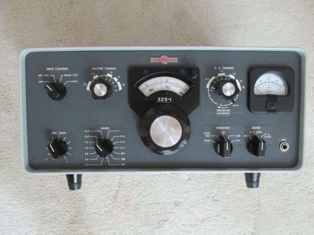
| 3.4–30 MHz (14 bands) | ~180 W PEP / ~100 W CW | USB / LSB / CW | 2 × 6146B (matched pair) | 6.3 V AC / 5 V AC |
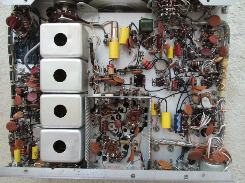
The Collins 32S-1 is a hallmark of precision SSB engineering from the late 1950s. Restoring one properly requires careful attention to aged electrolytics, wax coupling capacitors, selenium rectifiers, drifted resistors, and full RF/IF alignment. This guide provides a structured restoration framework including a curated vendor directory with direct links to suppliers for every component category.
⚠ SAFETY FIRST: Up to 800 V DC is present internally. Capacitors retain lethal charge after power-off. Always discharge filter caps through a 10 kΩ / 25 W bleeder before touching the chassis. Never work alone. Never bridge ground with your body.
1 · Component Replacement Master List
Every eBay-sourced unit should be treated as requiring a full recap and resistor audit before any RF power is applied. The table below lists all component categories with replacement specifications and vendor recommendations.
| Category | Components | Replacement Spec | Priority | Vendors |
|---|---|---|---|---|
| Electrolytic Capacitors | B+ filter caps (main PSU), cathode bypass, bias/ALC decoupling | 105°C rated, same or higher voltage. B+ filter: 40–100 µF / 450–500 V. Sprague Atom or F&T preferred. | CRITICAL | Amplified Parts (F&T, Sprague Atom) JustRadios OldRadioParts.net Mouser Electronics |
| Wax Coupling Caps (Bumblebee / Black Beauty) | All coupling, bypass & tuning caps in IF strip, carrier osc, balanced modulator, ALC chain | Replace ALL. Vishay Orange Drop 715P/716P, silver mica, or polypropylene film. 630 V or 1000 V as appropriate. | CRITICAL | Amplified Parts (Orange Drop, SoZo) JustRadios (630V/1000V film) Digi-Key (Vishay/Kemet) |
| Selenium Rectifiers | Bias supply rectifiers (2–4), AVC/ALC rectifiers | Replace with 1N4007 + 47–100 Ω / 1 W series resistor. Selenium emits toxic fumes when it fails. | CRITICAL | Amplified Parts (1N4007) Mouser (bulk 1N4007) Digi-Key |
| Carbon Composition Resistors | Grid/screen/cathode resistors, all R > 100 kΩ, bias chain | Drift of +50–200% is common. Replace drifted units with 1% metal film. Measure every resistor before ordering. | HIGH | Amplified Parts (metal film 1%) Mouser Digi-Key |
| Receiving Tubes | 12AX7 × 2, 12AU7, 6AQ5, 6CL6, 12BY7, 6BZ6, others | Test on TV-7 or MU-150. Replace below 70% Gm. Match pairs where required (balanced modulator). | HIGH | The Tube Store (tested NOS) Amplified Parts Radio Daze LLC NOSVacuumTubes.net |
| 6146B PA Finals (matched pair) | Q1, Q2 — PA finals. Always replace as a matched pair on eBay units. | Sylvania, RCA, or GE NOS preferred. Test for internal shorts before install. Modern Chinese 6146B vary widely in quality. | HIGH | The Tube Store (GE NOS 6146B) Radio Daze LLC (Sylvania matched pairs) NOSVacuumTubes.net |
| VFO Temp-Comp Capacitors | NPO/C0G caps in VFO, slug lock springs, air variable trimmers | Replace shifted NPO/C0G caps. Loose slug retaining springs cause severe frequency drift — inspect carefully. | MEDIUM | Mouser (NPO/C0G, silver mica) Digi-Key JustRadios |
| Carrier Oscillator Crystal | Y1 — 9.000 MHz carrier crystal, HC-6/U holder | Test for activity and correct frequency. If pulling range exhausted, replace. HC-6/U holder is standard. | MEDIUM | International Crystal Mfg. Mouser (stock 9 MHz HC-6/U) |
| Relay Contacts & T/R Relay | K1 T/R relay and all other relays | Clean contacts with DeoxIT Gold. Do NOT use abrasive on silver contacts. Replace coil if resistance is out of spec. | MEDIUM | CAIG Labs (DeoxIT Gold G5) Sweetwater |
| Potentiometers | DRIVE control, ALC threshold, carrier balance trimpot | Clean with DeoxIT D5 first. Replace scratchy pots. Use Cermet trimpots for alignment adjustments. | MEDIUM | CAIG Labs (DeoxIT D5) Amplified Parts (Alpha/Bourns) Mouser (Bourns Cermet trimpots) |
| Mains Wiring & Power Cord | AC power cord, fuse holder, X2/Y2 mains filter caps | Replace cracked cord with 3-prong grounded IEC C14 cable. Mains caps must be X2/Y2 safety-rated only. | HIGH | Mouser (IEC C14 inlet, X2/Y2 caps) Digi-Key (Schaffner FN2010 filter) Ham Radio Outlet |
| Band Switch Wafers | All band switch wafer contacts and wafer mounting hardware | Clean with DeoxIT F5 contact lubricant. Inspect for arc damage. Never use abrasive on wafer contacts. | MEDIUM | CAIG Labs (DeoxIT F5 Fader) Sweetwater (D5+F5 bundle) |
Tip: Document every removed component with a photograph and annotation on a printed schematic. The 32S-1 service manual (Collins doc 523-0406765) is available free from BAMA or as a reprint from Fair Radio Sales.
2 · Restoration Project Plan — Phase by Phase
Phase 1 — Initial Assessment & Documentation
- Photograph the chassis from all angles before touching anything.
- Download and print the 32S-1 service manual and schematic. Free PDF download from BAMA (bama.edebris.com).
- Inspect externally for signs of fire, arcing, melted wiring, or non-original modifications.
- Remove all tubes and label their socket positions. Set aside for testing.
- Visually inspect all capacitors for bulging, leakage, or carbonization.
- Inspect the power transformer for signs of overheating (varnish discoloration, cracked bobbin).
- Check the VFO assembly: look for broken slug lock springs, cracked coil forms, and loose trimmers.
- Record the serial number and any visible production date codes.
Phase 2 — Safety Preparation
- Replace the AC power cord with a 3-conductor grounded cable (IEC C14 conversion recommended). IEC inlets from Mouser or Digi-Key.
- Install a suitably-rated slow-blow fuse per the service manual.
- Discharge all electrolytic capacitors using a 10 kΩ / 25 W resistor for at least 30 seconds per cap.
- Verify chassis ground continuity from ground lug to power connector safety earth.
- Install a temporary series lamp limiter (100 W incandescent) in the AC line for all initial power-up tests.
Phase 3 — Passive Component Replacement (No Power Applied)
- Replace ALL electrolytic capacitors in the power supply section first. Source F&T or Sprague Atom from Amplified Parts or JustRadios.
- Replace ALL wax-impregnated coupling and bypass capacitors throughout the chassis. Orange Drop 715P/716P from Amplified Parts. Silver mica from JustRadios or Mouser.
- Replace all selenium rectifiers with 1N4007 + series resistor (47–100 Ω / 1 W). Bulk 1N4007 from Mouser.
- Measure all carbon composition resistors. Replace drifted units with 1% metal film. Assortment kits from Amplified Parts.
- Inspect and clean band switch wafers with DeoxIT F5 (CAIG Labs).
- Clean relay contacts with DeoxIT Gold G5.
- Check and lubricate the tuning mechanism and variable capacitor bearings with Nye Clock Oil or similar.
Phase 4 — First Power-Up (Lamp Limiter In-Line)
- Reinstall rectifier tubes only (or confirm silicon replacements are in place). Do NOT install PA tubes yet.
- Apply power through the lamp limiter. Brief flicker then dim = normal behaviour.
- Measure B+ at test points per the service manual. Typical: ~400–450 V at filter output, ~250 V screen supply.
- Check all regulated voltages: ALC, bias, and VFO supply rails.
- Allow 30 minutes for capacitor reforming under observation. Check for heat, odor, or distress.
- If all voltages are correct, remove the lamp limiter for subsequent tests.
Phase 5 — Tube Reinstatement & Bias Setting
- Test all receiving tubes on a calibrated emission tester (TV-7, MU-150). Source tested replacements from The Tube Store or Amplified Parts.
- Install receiving tubes section by section, measuring idle current at each stage.
- Install a matched pair of new 6146B finals. NOS pairs from The Tube Store or Radio Daze LLC.
- Set PA cathode bias per the service manual TUNE/OPERATE procedure. Target: 20–30 mA combined idle.
- Check for plate redness on the PA tubes at idle — visible redness means bias is too hot.
Phase 6 — IF Strip & Carrier Oscillator Alignment
- Confirm the carrier oscillator is on frequency (9.000 MHz) using a calibrated frequency counter at the carrier injection point.
- Align the balanced modulator for maximum carrier suppression — target greater than 40 dB below PEP.
- Align IF transformers T1–T4 for correct SSB passband shape using a signal generator and oscilloscope.
- Replacement carrier crystals (9.000 MHz, HC-6/U) from International Crystal Mfg. if required.
Phase 7 — RF Section & BPF Alignment
- Connect a calibrated 50 Ω dummy load (200 W+) to the antenna output. Bird 43 wattmeter from Bird Technologies or Ham Radio Outlet.
- Align the bandpass filters for each of the 14 bands using a spectrum analyzer. Budget option: TinySA Ultra (Amazon) — 100 kHz to 5.3 GHz, well suited to harmonic work.
- Driver neutralization: follow the service manual procedure per band.
- Check exciter output level and DRIVE setting for rated output.
Phase 8 — PA TUNE / OPERATE & Final Testing
- TUNE: Dip the PA plate current to minimum (resonance) using the TUNE control.
- LOAD: Increase loading while maintaining the dip, for maximum power output into the dummy load.
- Target output: ~100 W CW / ~180 W PEP SSB into 50 Ω.
- Repeat alignment on all 14 bands. Document output power per band.
- Conduct a two-tone IMD test (700 Hz + 1900 Hz). Target: 3rd-order products ≥ −30 dBc.
3 · RFI Prevention
Aging wiring, failed bypass capacitors, and ungrounded shields can turn the 32S-1 into a broadband interference source. The following measures address both conducted and radiated RFI.
3.1 — AC Mains Filtering
- Install a commercial mains line filter such as the Schaffner FN2010 series in series with the AC input. Available from Mouser and Digi-Key.
- Replace any mains-side X/Y capacitors with modern X2/Y2 rated devices only.
- Route the AC power lead away from RF wiring inside the chassis.
3.2 — Bypass Capacitor Integrity
- Add a 0.01 µF ceramic disc in parallel with each electrolytic B+ filter cap to shunt RF components. Ceramic disc caps from Mouser.
- Inspect all ground return points on bypass cap leads — cold solder joints are a common RFI source.
3.3 — Shield Integrity & Chassis Grounding
- Inspect all internal RF shields — verify all shield screws are present and tight.
- Clean shield-to-chassis contact surfaces with DeoxIT D5 to ensure metal-to-metal contact.
- The bottom cover must be in place during operation — it is an integral part of the RF shielding.
3.4 — Audio & Control Lead Routing
- Route microphone and audio leads away from the RF chain. Use shielded cable for the mic lead, shield grounded at the transceiver end only.
- Add ferrite beads (Fair-Rite #43 or #31 material) to the mic cable, PTT line, and accessory control cables at the chassis entry point. Available from Fair-Rite Products or Mouser.
3.5 — Operating Environment
- Ensure the antenna system presents SWR < 2:1 — high SWR causes RF on the chassis and mains wiring.
- Use a current-mode common-mode choke (1:1 choke balun) at the antenna feedpoint. Available from DX Engineering and Ham Radio Outlet.
- Star grounding topology in the shack — all equipment to a single ground point.
4 · Electrical Shock Safety
HIGH VOLTAGE HAZARD — UP TO 800 V DC. These voltages cause ventricular fibrillation at currents as low as 100 mA. Capacitors can retain lethal charge for years after power-off. ALWAYS verify zero volts with a calibrated meter before touching any internal node.
4.1 — Before Opening the Chassis
- Power off and disconnect the AC mains cord from the wall — not just at the power switch.
- Discharge all filter capacitors through a 10 kΩ / 25 W resistor for at least 30 seconds per cap.
- Verify zero volts with a calibrated DMM (Fluke 87V or equivalent, rated 1000 V CAT II) on the 1000 V DC range before touching any component. DMMs from Fluke or Ham Radio Outlet.
4.2 — Safe Working Practice
- One-hand rule: work with one hand inside the chassis whenever possible. Keep the other hand behind your back or in a pocket.
- Never work alone on a live chassis.
- Use insulated probes rated for at least 1000 V CAT II.
- Wear safety glasses — electrolytic capacitors can rupture under fault conditions.
4.3 — Chassis Grounding & Earth Safety
- The 32S-1 chassis MUST be connected to mains protective earth (PE) via the power cord ground conductor.
- Verify chassis-to-PE continuity is less than 1 Ω after replacing the power cord.
- IEC C14 inlet conversion hardware from Mouser or Digi-Key.
4.4 — PA Tube Handling
- 6146B tubes run hot — allow at least 10 minutes after power-off before handling.
- Never operate the PA without a properly matched load. Suitable 200 W dummy loads from DX Engineering or Ham Radio Outlet.
- Check 6146B socket pins for proper seating before applying power.
4.5 — Test Equipment Safety
- When connecting a spectrum analyzer, place a suitable RF attenuator in-line on the antenna port. Even brief transmit pulses can destroy a spectrum analyzer input.
- Use a differential probe or isolation transformer when measuring non-ground-referenced nodes.
5 · Signal Purity & Harmonic Suppression
The 32S-1 is capable of excellent signal purity when properly aligned. This section covers harmonic suppression, IMD, carrier and sideband suppression, and the measurement procedures required to confirm regulatory compliance under ACMA Technical Standard TS 101.
5.1 — Low-Pass Output Filter Integrity
- Verify all LPF coils are intact. Replace LPF shunt capacitors (silver mica or high-Q ceramic) if any have shifted. Silver mica from JustRadios and Mouser.
- Target: all harmonics at least −40 dBc below PEP output per ACMA/FCC amateur rules.
5.2 — PA Neutralization & Linearity
- Verify PA neutralization per the service manual. Set DRIVE to the minimum level that achieves rated output.
- ALC action should begin at approximately rated PEP. Premature ALC causes IMD products.
5.3 — Carrier & Unwanted Sideband Suppression
- Adjust the balanced modulator null for −40 dBc carrier suppression on a spectrum analyzer. Budget analyzer: TinySA Ultra (Amazon).
- Balanced modulator diodes (1N34A germanium matched set): replace if leaky or mismatched. Available from Amplified Parts or Mouser.
- Target unwanted sideband suppression: ≥ −40 dBc below PEP.
5.4 — VFO Spectral Purity
- Acceptable frequency drift: < 100 Hz over 30 minutes warm-up after a proper warm-up period.
- Check the VFO buffer stage for correct operating point — over-driving the buffer generates harmonic-rich output.
- VFO spurious: no spurs within 10 kHz above −60 dBc.
5.5 — Two-Tone IMD Test Procedure
- Connect a two-tone audio generator (700 Hz + 1900 Hz, equal amplitude, resistive combiner) to the microphone input. A PC audio interface with signal generator software can serve this purpose.
- Third-order IMD products should be at least −30 dBc. A well-aligned 32S-1 achieves −35 to −40 dBc.
- Document the IMD result as a baseline for ongoing monitoring.
Spectrum Analyzer Verification Checklist
- All harmonics: −40 dBc or better (2nd, 3rd, 4th — check all 14 bands)
- Carrier suppression: −40 dBc or better below PEP
- Unwanted sideband: −40 dBc or better below PEP
- 3rd-order IMD: −30 dBc or better below reference tone (two-tone test)
- VFO spurious: no spurs within 10 kHz above −60 dBc
- SSB transmitted bandwidth: ≤ 2.4 kHz for voice operation
6 · Recommended Tools & Test Equipment
| Item | Specification | Purpose | Where to Buy |
|---|---|---|---|
| Digital Multimeter | Fluke 87V, 1000 V CAT II rated | Voltage, resistance, continuity | fluke.com · Ham Radio Outlet |
| Frequency Counter | 1 Hz resolution, 30 MHz+ | Carrier oscillator / VFO verification | Mouser · Ham Radio Outlet |
| Oscilloscope | 2-ch, 100 MHz, 10× probes | Waveform inspection, modulation | Digi-Key · Ham Radio Outlet |
| Spectrum Analyzer | TinySA Ultra (budget) or HP8566 (lab) | Harmonic, spurious, IMD measurement | Amazon (TinySA Ultra) · tinySA.org (official) |
| RF Wattmeter | Bird 43 with 100 W / 200 W slug, 50 Ω | Output power measurement | Bird Technologies · Ham Radio Outlet · DX Engineering |
| Dummy Load | 50 Ω non-inductive, 200 W continuous | Safe PA testing without antenna | DX Engineering · Ham Radio Outlet |
| Tube Tester | TV-7D/U or MU-150, calibrated | Tube emission and Gm testing | eBay (NOS testers) · AntiqueRadio.org Parts |
| LCR Meter | DE-5000 or equivalent | Cap / inductor value verification | Amazon (DE-5000) · Mouser |
| Desoldering Station | Hakko FR-301 or Pace MBT250 | Clean component removal | Amplified Parts · Amazon |
| Contact Cleaner Kit | DeoxIT D5, F5 Fader, Gold G5 (CAIG) | Switch, relay, pot, wafer cleaning | caig.com · Sweetwater (D5+F5 bundle) |
| Service Manual | Collins 32S-1 doc 523-0406765 | Essential alignment reference | BAMA (free PDF) · Fair Radio Sales (reprint) |
7 · Vendor Directory
Curated vendor list for all restoration component categories. Always confirm stock and pricing before ordering — the vintage component market moves quickly.
Capacitors — Electrolytic, Film, Silver Mica
| Amplified Parts (formerly AES) | F&T electrolytics, Sprague Atom, Orange Drop 715P/716P, SoZo Yellow Mustard. Excellent range of high-voltage film and electrolytic caps specifically for tube equipment. |
| JustRadios | Specialist in high-voltage capacitors for tube radios. Stocks hard-to-find MFD sizes (2, 4, 8, 16, 20, 40, 50, 80 µF) commonly used in Collins and vintage gear. Old-school email ordering. |
| OldRadioParts.net | Discount pricing on new high-voltage electrolytic capacitors for antique radios and tube amplifiers. |
| Mouser Electronics | Global authorised distributor. Full range of Vishay, Kemet, Cornell-Dubilier, Panasonic, Nichicon capacitors. Excellent for X2/Y2 safety caps and NPO/C0G precision types. |
| Digi-Key Electronics | Global distributor. Strong on Vishay film caps, Cornell-Dubilier electrolytics, and precision silver mica. Good for IEC inlet hardware and mains filtering components. |
Vacuum Tubes
| The Tube Store | Tested NOS tubes including GE 6146B matched pairs for the 32S-1 PA finals. Stocks receiving tubes 12AX7, 12AU7, 6AQ5, 6BZ6 and others. Ships to Australia. 3-month guarantee on all tubes. |
| Radio Daze LLC | Specialises in NOS matched pairs for ham radio transmitters. Carries Sylvania and GE 6146B/8298A matched pairs tested on Hickok AN/USM-118B. Matching parameters documented per pair. |
| NOSVacuumTubes.net | Precision tested NOS tubes. Sylvania 6146B in stock. Good for the full receiving tube complement. |
| Amplified Parts | Broad selection of receiving tubes including matched pairs for audio and SSB stages. |
Resistors
| Amplified Parts | Metal film 1%, carbon composition (for authenticity), and wirewound power resistors including Ohmite Brown Devil series. Bulk discounts available. |
| Mouser Electronics | Full range of Vishay/Dale, Ohmite, and KOA metal film and wirewound resistors. Use the parametric search to filter by wattage, tolerance, and value. |
Contact Cleaners & Lubricants
| CAIG Laboratories | The definitive source for DeoxIT D5 (general contact cleaner), Gold G5 (relay and switch contacts), and F5 Fader (band switch wafers and potentiometers). Essential for any S-Line restoration. |
| Sweetwater Sound | Convenient retail source for CAIG DeoxIT D5 + F5 bundle and DeoxIT Gold G5. Fast shipping. |
Crystals
| International Crystal Mfg. | Custom and stock HC-6/U crystals. Can supply 9.000 MHz carrier crystals for the 32S-1 balanced modulator. Custom frequencies available with short lead times. |
| Mouser Electronics | Stocks standard 9 MHz crystals in HC-6/U holders from multiple manufacturers. |
RF Test Equipment
| Bird Technologies | Manufacturers of the Bird Model 43 wattmeter and RF slugs — the gold standard for transmitter output power measurement. 100 W and 200 W slugs are the right range for 32S-1 testing. |
| Ham Radio Outlet | Full-service US ham radio dealer. Stocks Bird 43, dummy loads, frequency counters, and general test equipment. Multiple US locations; ships internationally. |
| DX Engineering | Technical ham radio supplier. Stocks dummy loads (200 W+), current-mode choke baluns, feedline accessories, and antenna hardware for proper transmitter loading. |
| TinySA Ultra (official site) | Official site for the open-source TinySA spectrum analyzer project. Purchase from authorised vendors listed at the site to avoid counterfeits. The Ultra model (100 kHz–5.3 GHz) is well suited to harmonic checking on HF transmitters. Also available via Amazon — confirm seller is on the approved vendor list. |
RFI Components — Ferrite & Mains Filters
| Fair-Rite Products Corp. | Primary manufacturer of ferrite materials for EMI suppression. #43 material (best for 1–50 MHz) and #31 material (HF–VHF) clamp-on cores for mic cables, control leads, and PTT lines. |
| Mouser Electronics | Full Fair-Rite product line stocked. Also carries Schaffner FN2010 mains line filters and Würth Elektronik EMI suppression components. |
Service Manuals & Documentation
| BAMA — Boat Anchor Manual Archive | Free PDF downloads of the Collins 32S-1 service manual (doc 523-0406765) and virtually every other vintage ham radio manual. An indispensable resource for any boatanchor restoration. |
| Fair Radio Sales | Military and commercial electronics surplus including Collins equipment and reprinted manuals. Source for hard-to-find Collins accessories and surplus components. |
| AntiqueRadio.org Parts Guide | Comprehensive directory of vintage radio parts and information sources. Good starting point for less common requirements. |
8 · References
- Collins 32S-1 Service Manual, document 523-0406765 — free PDF: bama.edebris.com
- Collins S-Line Alignment Procedures, Hollow State Newsletter — archived at vk6ada.com.au/hollow-state-newsletter
- ARRL Handbook for Radio Communications — SSB Transmitter Testing and Alignment
- Eimac: Care and Feeding of Power Grid Tubes — PA operating point and dissipation guidance
- ITU-R SM.329 — Spurious emission limits for amateur radio transmitters
- ACMA Technical Standard TS 101 — Australian Amateur Radio apparatus licence technical conditions
- Fair-Rite Products Corp. Ferrite Material Selection Guide: fair-rite.com
- TinySA Ultra project documentation: tinySA.org
Mike Peace VK6ADA / r-390a.net Administrator
Collins 32S-1 Transmitter Restoration Guide · March 2026 · vk6ada.com.au
Ebay auction: 305003758321