Collins 75A-4 Known Issues & Top Components to Replace
The Seven Deadly Caps, BFO Injection Level, Detector Diode Aging & IF Transformer Core Crumbling
The receiver that bridges the 51J era and the S-Line — a consolidated restoration reference with the complete Rippel/Schartau/Solomon capacitor priority list and community-proven fixes for the most common 75A-4 faults
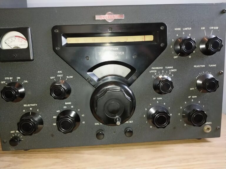
The Collins 75A-4 (1955–1958) is the final and most sophisticated receiver in the Collins A-Line series. It was the world’s first SSB-optimised amateur receiver, replacing the crystal filter of earlier A-Line models with plug-in Collins Mechanical Filters, a Q-multiplier rejection notch, passband tuning, and a dedicated CW/SSB product detector. Approximately 5,840 units were manufactured. The 75A-4 bridges the 51J-era general-coverage receivers and the S-Line that followed, and it remains a benchmark for AM and SSB reception quality when properly restored.[1]
The 75A-4 has a well-documented set of age-related component failures that, collectively, produce the most common complaint heard about these receivers: “low gain, audio popping, and distortion.” Chuck Rippel identified the core of the problem in his famous “Seven Deadly Caps” list, which was later expanded by Butch Schartau K0BS, Jerry Solomon, and other community contributors into the comprehensive replacement priority list presented here.[2]
Chuck Rippel pinpointed the source of the 75A-4’s most common performance complaints to seven interstage coupling capacitors that develop DC leakage with age. These mica and ceramic capacitors couple the plate of one stage to the grid of the next; when they leak, they inject DC offset onto the following grid, corrupting bias, reducing gain, and producing audio distortion and popping. A standard digital multimeter will not detect this leakage — the 9V test voltage is insufficient to cause the degraded capacitor to conduct. A megger (insulation resistance tester) or a dedicated capacitor leakage tester operating at the working voltage is required.[2]
| Ref. Des. | Value | Location | Function | Replacement |
|---|---|---|---|---|
C-34 | 100 pF | V-3 Pin 3 | Interstage coupling | Dipped mica 500V |
C-52 | 4 pF | V-5 Pin 7 | 2 MHz IF coupling | Dipped mica 500V |
C-68 | 470 pF | V-7 Pin 2 | Interstage coupling | Dipped mica 500V |
C-75 | 470 pF | V-8 Pin 1 | Interstage coupling | Dipped mica 500V |
C-81 | 470 pF | V-9 Pin 1 | Interstage coupling | Dipped mica 500V |
C-101 | 0.01 µF | V-22 Pin 1 | Audio coupling | Orange Drop 600V |
C-104 | 470 pF | V-21 Pin 1 | Interstage coupling | Dipped mica 500V |
| Ref. Des. | Value | Location | Notes | Replacement |
|---|---|---|---|---|
C-71 | 1000 pF | V-7 Pin 6 | Known high failure item | Dipped mica 500V |
C-95 | 0.01 µF | V-11 Pin 6 | Product detector circuit | Orange Drop 600V |
C-96 | 0.01 µF | V-12 Pin 2 | Noise limiter circuit | Orange Drop 600V |
| Ref. Des. | Value | Location | Notes | Replacement |
|---|---|---|---|---|
C-147 | — | V-12 Pin 1 | Noise limiter / audio | Equivalent film type |
C-148 | — | V-12 Pin 2/5 | Noise limiter / audio | Equivalent film type |
C-37 | — | — | N1EU addition | Equivalent type |
C-92 | — | — | N1EU addition | Equivalent type |
C-93 | — | — | N1EU addition | Equivalent type |
C-100 | — | — | N1EU addition | Equivalent type |
| Ref. Des. | Value | Function | Notes | Replacement |
|---|---|---|---|---|
C-94 a,b,c | 40/40/40 µF 300V | HV supply triple electrolytic | Goes out fast after storage — reform carefully | CE FP can or individual radials |
C-113 | 50 µF 150V | Bias supply | Exposed to higher-than-rated voltage | Higher WV electrolytic |
C-137 | 50 µF 150V | Bias supply | Exposed to higher-than-rated voltage | Higher WV electrolytic |
C-124 | 0.5 µF 200V | B+ bypass | Collins schematic lists incorrectly as 0.5 mmF | 0.47 µF 400V film |
| Ref. Des. | Notes |
|---|---|
C20, C62, C70, C97, C98, C108, C111, C112, C115, C116, C146 | All Sprague Black Beauty oiled paper capacitors — replace all with Orange Drop or equivalent film types. There are so few good Black Beauties remaining that individual testing is not cost-effective.[3] |
⚠ Priority: Replace the Seven Deadly Caps, the extended mica list, the Black Beauties, and the electrolytics before any alignment or performance measurement. Until these components are replaced, every other test result is unreliable.
Symptom: The receiver overloads on strong signals before the AGC brings the gain down. SSB reception sounds compressed or distorted on signals above S9. The AGC appears too slow to react to initial signal peaks.[3]
Root Cause: The 75A-4 AGC attack time is too slow to react to the first few cycles of an SSB signal, allowing the IF and audio stages to overload before the AGC voltage reaches its correct level. This is a design-era limitation that every unmodified 75A-4 exhibits. Leaky mica capacitors in the AGC circuit exacerbate the problem by corrupting the AGC time constant.
Fix: The W1LSB AGC modification is the most widely adopted. Replace any leaky mica capacitors in the AGC circuit first. For the slow AGC position on SSB, a 5.0 MΩ resistor in place of the 3.3 MΩ standard value extends the hold time to approximately 1 second — significantly improving SSB listening comfort. This modification is documented in the CCA Technical Data Sheet A97-001 (K7CMS modifications).[3]
Symptom: SSB audio sounds distorted or harsh; CW signals have poor quality; the BFO seems either too strong (overloading the product detector) or too weak (insufficient carrier reinsertion).[4]
Root Cause: The BFO (V-20) injection level to the CW/SSB product detector (V-11) is critical — too much BFO injection overdrives the mixer and produces distortion products; too little produces weak, distorted audio. The K7CMS modification addresses this by reducing the IF signal injection level to the product detector. Additionally, a bad ground connection on the BFO can — one of the most common hidden faults in the 75A-4 — can alter the BFO injection level unpredictably.[3]
Fix: Verify the ground connection on the BFO can (V-20 shield enclosure) is clean and tight — this single ground fault has been documented as causing weeks of frustrating troubleshooting. If BFO injection is still incorrect after confirming grounds, refer to the K7CMS modification which adds a 470 kΩ resistor between C-100 (0.01 µF) and V-13 pin 7 (12AT7) to reduce IF signal level at the product detector, and reverses the primary leads of the audio output transformer (T-5) while relocating the feedback resistor R-71 from V-13 pin 3 to pin 8.[4]
Symptom: AM audio sounds distorted on strong signals; the noise limiter (V-12, 6AL5) is ineffective or clips normal audio; sensitivity to strong-signal overloading is worse than expected.[1]
Root Cause: The AM detector uses a conventional diode rectifier section of V-16 (twin diode), and the noise limiter uses V-12 (6AL5). After decades of service, these diode sections develop increased forward resistance, reduced peak current capability, and drift in their contact potential. The AVC noise clipper (the other half of V-16) can also degrade, allowing noise pulses through to desensitise the AVC circuit. Leaky coupling capacitors C-95/C-96 in the detector and noise limiter circuits compound these tube aging effects.[2]
Fix: Replace V-12 (6AL5) and V-16 with fresh tubes. Replace C-95 and C-96 per the Schartau K0BS extended cap list. Check the AVC delay voltage on V-16 — a small positive DC voltage should be present via R-86 to provide AVC delay for weak signals; if this voltage is incorrect, the detector operating point is wrong.
Symptom: Alignment cannot be achieved on the 455 kHz IF transformers; a slug turns freely without producing a tuning peak; grey or brown powder falls out when the transformer is inverted; sensitivity drops on one or more IF stages.[5]
Root Cause: The powdered-iron or ferrite slugs in the 455 kHz IF transformers (T-1 through T-4) can physically deteriorate over decades, crumbling into powder. This is a material aging issue — moisture ingress, thermal cycling, and oxidation of the iron powder binder cause the slug to lose structural integrity. When the slug crumbles, it no longer provides the permeability needed to tune the transformer to resonance.
Fix: If the slug is damaged but the coil and can are intact, replacement slugs are available from specialty suppliers (Aladdin, CWS ByteMark, or salvage from donor transformers). If the entire transformer assembly is damaged, complete replacement IF transformers must be sourced from donor 75A-4 receivers. The CCA vendor directory lists sources for these components. Prevention is straightforward: never force a stuck slug, and never use a metal alignment tool that might chip the slug.
Inspection Tip: During any 75A-4 restoration, gently attempt to turn each IF transformer slug. If it turns freely without resistance and produces no change in receiver output, the slug is likely crumbled. If it is stuck solid, apply the minimum force necessary — a stuck slug is better than a broken one.
Symptom: No signal in one or more filter positions; intermittent audio with the selectivity switch; crackling when the selectivity switch is operated.[1]
Root Cause: The 75A-4 uses plug-in F455J-series mechanical filters in 9-pin miniature tube sockets. The socket contacts can develop oxidation, and the filter pins can develop tarnish. Missing filters (the 75A-4 was supplied with only the F455J-31 standard filter; the F455J-05 and F455J-60 were optional) leave empty sockets that some operators never filled.
Fix: Clean the 9-pin miniature sockets with DeoxIT and a socket cleaning tool. Clean the filter pins with a fine abrasive contact cleaner. Verify that the correct filter is installed in the correct socket position. The standard filter complement is: F455J-05 (0.5 kHz CW, P/N 526-9154-00), F455J-31 (3.1 kHz SSB/AM, P/N 526-9089-00), and F455J-60 (6.0 kHz AM, P/N 526-9091-00).[1]
Cross-Reference: See the separate Collins IF Selectivity Filter Master Reference on this site for complete F455J mechanical filter specifications, part numbers, and case style details.
Symptom: Intermittent oscillation; sensitivity changes when the chassis is tapped or flexed; one specific problem that “escaped for three weeks” before being traced to a bad ground on the BFO can.[3]
Root Cause: After 60+ years, cadmium-plated chassis ground connections develop high-resistance oxide films. The 75A-4 has numerous critical ground points — on transformer cans, tube socket shields, switch wafer ground connections, and the BFO enclosure — where a degraded ground produces symptoms that mimic component failures.
Fix: Systematically clean all ground connections using contact cleaner and a star washer to bite through the oxide film. Pay particular attention to the BFO can ground, the IF transformer can grounds, and the mechanical filter socket ground connections. “Make sure all the ground connections are good” before looking for component-level faults — this is the most frequently repeated advice from experienced 75A-4 restorers.[3]
Symptom: The passband tuning control provides some rejection but does not approach the performance of electronic passband tuning in later receivers such as the Drake R-4C.[5]
Root Cause: The 75A-4’s passband tuning operates by shifting the VFO frequency relative to the mechanical filter passband — a technique Collins described as “pseudo passband tuning.” This moves the received signal through the fixed filter passband but does not independently control the upper and lower edges of the passband as electronic passband tuning does.
Fix: This is a design characteristic, not a fault. For operators requiring true passband tuning, an external dual-filter electronic passband tuning system can be built using aftermarket IF filters. However, most operators find the stock passband tuning adequate for normal amateur operation when the mechanical filters are in good condition and properly aligned.
| Bulletin | Description | Priority |
|---|---|---|
SB-1 | Removal of B+ from the mechanical filter circuit — prevents filter damage from shorted coupling capacitor | Critical — verify on all units |
SB-4 | S-Meter zero stabilisation; corrects R86 design error | Recommended |
⚠ SB-1 Critical: Service Bulletin SB-1 addresses the same class of failure that destroys R-390A mechanical filters — a coupling capacitor shorting and putting B+ directly onto the mechanical filter input winding. Verify that SB-1 has been implemented in any 75A-4 before applying power. If in doubt, check for the modification described in the bulletin before powering up.
- Collins Collectors Association — 75A-4 Equipment Profile. Mechanical filter complement (F455J-05/31/60), Q-multiplier rejection tuning, AVC circuit (V-16 twin diode), AM/CW-SSB dual detector architecture, passband tuning. collinsradio.org — 75A-4
- Rippel, Chuck. Collins 75A-4 Receiver 7 Deadly Caps. Original identification of the seven interstage coupling capacitors causing low gain, audio popping, and distortion. CCA publication. collinsradio.org — 7 Deadly Caps
- N1EU. 75A-4 Mod Notes. Complete consolidated capacitor list (Rippel/Schartau/Solomon/N1EU additions), BFO ground fault documentation, AGC modification details, K7CMS and N0DMS modification descriptions, megger testing requirement. qsl.net/n1eu — 75A-4 Mods
- Collins Reflector. 75A-4 Sensitivity Problem — K7CMS Modifications. Product detector IF signal level reduction, audio output transformer feedback rearrangement, SSB distortion reduction. Electric Radio Issue #13, May 1990. Collins Reflector — K7CMS Mods
- Antique Radio Forums. Starting the 75A-4 Restoration. Community discussion of capacitor replacement strategy, AGC modification options, passband tuning limitations, “Seven Deadly Caps” implementation, Collins workmanship quality. January 2021. antiqueradios.com — 75A-4 Restoration
- Collins Reflector. 75A-4 Cap Answers (Updated). Complete capacitor list with testing methodology (megger vs. DVM), freeze-mist diagnostic technique, Black Beauty identification guide. June 2002. Collins Reflector — Cap Answers
- Collins Collectors Association — RX For Your Collins. Master index including: “The Seven Deadly Caps — Ripple,” “Stabilize S-Meter zero & Corrects R86 Design Error (SB-4),” “Make sure you have accomplished SB-1 (removal of B+ from the Mech. Filter).” collinsradio.org — RX For Your Collins
- Collins 75A-4 Amateur-Band Receiver Instruction Book, 3rd Edition (March 1957). Circuit description, alignment procedures, service notes, mechanical filter installation. collinsradio.org — 75A-4 Manual Section 5 (PDF)
- Radiomuseum.org — Collins 75A-4. Production quantity (~5,840 units), mechanical filter types, four-step crystal filter, two-speed AGC, passband tuning. radiomuseum.org — 75A-4
Chuck Rippel — For the original “Seven Deadly Caps” identification that forms the foundation of every 75A-4 restoration.
Butch Schartau, K0BS — For the extended capacitor failure list that added C-71, C-95, and C-96 to the priority replacement table.
Jerry Solomon — For the C-147/C-148 additions to the capacitor list.
N1EU — For the comprehensive consolidated mod notes page that brings together the Rippel/Schartau/Solomon lists with the K7CMS, N0DMS, and W1LSB modifications.
William H. Beatty, K7CMS — For the audio feedback rearrangement and SSB distortion reduction modifications (Electric Radio Issue #13, 1990).
Rodger WQ9E — For the pragmatic advice to replace the known-bad capacitors and apply the factory service bulletins before considering any further modifications: “The 75A-4 is a great receiver that is easy to destroy via hammy hambone modification.”
Collins Collectors Association (CCA) — For hosting the Rippel “Seven Deadly Caps” article and the “RX For Your Collins” resource library including SB-1 and SB-4 documentation.