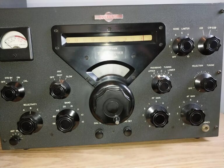
Collins 75A-4 Amateur Receiver
Failure Prevention Kit — Component & Modification Design
A complete engineering analysis of the ten predictable 75A-4 failure modes: power supply and paper capacitor ageing, the Collins FL-10 mechanical filter transducer lead fracture, carbon composition resistor drift in the IF section, Collins 70H-12 PTO lubrication, 0A2 voltage regulator failure, product detector and BFO carrier injection drift, USB/LSB sideband switching contacts, band switch oxidation, and line voltage overstress. The 75A-4 is the culmination of the Black Box series — the first Collins amateur receiver with a mechanical filter and independent USB/LSB sideband selection. Produced c. 1958–1981, it is the longest-running 75A design and the most capable. Covers all production versions.
The Collins 75A-4 is the final and most capable receiver in the Black Box series. Two changes define it against the 75A-3: the crystal bandpass filter was replaced by the Collins FL-10 mechanical filter, and a USB/LSB sideband switch was added, making the 75A-4 the first receiver in the series to independently select upper and lower sideband. The mechanical filter gave the 75A-4 a selectivity profile that was, for its era, unmatched in an amateur receiver — sharper skirts, lower insertion loss, and lower in-band phase distortion than any crystal filter arrangement. The 75A-4 was produced from approximately 1958 to 1981, an exceptionally long production run that overlapped the S-Line era and continued well into the decade after Collins ceased domestic amateur production.
The 75A-4 shares most of its architecture with the 75A-3 — the same Collins 70H-12 PTO, the same 0A2 voltage regulator, the same 6BE6 product detector — but it introduces one failure mode with no equivalent in any earlier 75A model: FL-10 mechanical filter transducer lead fracture. A failed FL-10 filter cannot be repaired in the field. It requires an NOS replacement filter, which is increasingly difficult to source. Physical shock from mishandling the receiver is the primary cause, and it is entirely preventable. This guide documents all ten predictable failure modes including the mechanical filter risk in full, and the restoration kit required to address all of them.
After 65–67 years, every electrolytic and paper capacitor in the 75A-4 requires replacement without exception. The IF section carbon composition resistors must be measured before any alignment. The 70H-12 PTO requires lubrication service, and the 0A2 regulator tube must be tested under power. A 75A-4 in unrestored condition should not be operated; restoration is the prerequisite for reliable station service.
Section 1 — Receiver Overview
Design Generation and Station Context
The 75A-4 arrived as the S-Line era was beginning. Collins designed it as the companion receiver to the 32S-1 and 32S-3 transmitters, and it was commonly paired with the 516F-2 power supply and 312B-4 or 312B-5 speaker/console in a matching station configuration. The front panel cosmetics, particularly in later production, echo the S-Line styling. When combined with a 32S-3 and 516F-2, the 75A-4 forms arguably the definitive expression of the Collins amateur station as it was conceived in the late 1950s.
The receiver uses double conversion on all bands except 160 metres (single conversion), with the variable first IF tuned by the Collins 70H-12 PTO. The second conversion produces a 455 kc IF. The Collins FL-10 series mechanical filter provides selectivity at this second IF. The product detector (V9, 6BE6) and BFO (V10, 6C4) resolve SSB and CW. The MODE control provides AM, USB, LSB, and CW positions. The USB/LSB selection shifts the BFO injection frequency relative to the IF passband to select the desired sideband via the mechanical filter’s offset characteristics.
Production Versions
The 75A-4 was in production from approximately 1958 to 1981. Production changes over this span are documented in service bulletins held by the Collins Collectors Association (CCA). Most substantive differences relate to minor circuit changes, revised component values, and cosmetic updates to match contemporary S-Line styling. The mechanical filter type may vary by production date: early units used the FL-10 series; some later units may carry FL-44 or related types at the same IF frequency. Verify the installed filter part number against the service bulletin record before ordering a replacement. All restoration procedures in this guide apply to all production versions; service manual errata for specific serial number ranges are documented in the CCA archive.
Tube Complement
Section 2 — The Ten Predictable Failure Modes
All ten failure modes are age-related and predictable. Failure modes F-01 through F-06 are Tier 1: they must be addressed before any powered operation. F-03 (mechanical filter) is technically a Tier 2 service risk in terms of discovery sequence, but the consequences of filter loss are severe enough to warrant Tier 1 handling attention from the moment the receiver arrives on the bench. Failure modes F-07 through F-10 are Tier 2.
-
F-01
Power supply electrolytic capacitors TIER 1 — MANDATORY The 75A-4 power supply contains multiple electrolytic capacitors in the B+ filter chain, screen bypass positions, and audio section. After 65–67 years, these have lost capacitance, elevated ESR, and in many cases absorbed moisture into the electrolyte. Symptoms: audible 120 Hz hum in received audio (main B+ filter capacitors), motorboating under strong signals (screen bypass capacitors), or supply voltage sag during voice-peak loading. No electrolytic should be retained regardless of ESR meter readings; the internal construction of period capacitors makes ambient-temperature bench measurements unreliable. Replace: main B+ filter (dual-section or equivalent, verify rating from service manual), screen bypass capacitors for all three 6BA6 IF stages (V5/V6/V7), and audio section bypass capacitors. Use 105°C rated modern electrolytics throughout. Do not power up until replacement is complete.
-
F-02
Paper, wax, and tubular capacitor replacement TIER 1 — MANDATORY The 75A-4 contains approximately 30–35 paper and wax-impregnated tubular capacitors in the RF section, variable IF section, 455 kc IF section, product detector and BFO circuits, and power supply. These fail as either leaky (partial DC conduction through the dielectric, producing incorrect tube grid bias without overt catastrophic symptoms) or short-circuit (complete dielectric failure, potentially damaging associated tubes or transformers). Replace all paper and wax types with modern polypropylene or polyester film capacitors of equal or greater voltage rating. Critical exception: the PTO buffer/output coupling capacitor must be replaced with silver mica only — film types introduce microphonic and temperature-coefficient frequency modulation into the 70H-12 PTO output, degrading SSB stability. The correct silver mica value is specified in the service manual. Mark this capacitor on the parts list before beginning the recap session.
-
F-03
Collins FL-10 mechanical filter — transducer lead fracture and insertion loss TIER 1 HANDLING — NOT FIELD REPAIRABLE The Collins FL-10 mechanical filter is the defining component of the 75A-4 and its most catastrophically irreplaceable part. The filter uses nickel-alloy mechanical resonators coupled by precision metal discs, with magnetostrictive transducers at input and output. Two failure mechanisms are documented:
(a) Transducer lead fracture. The solder joints connecting the input and output transducer leads to the filter body are subject to thermal cycling fatigue and physical shock fracture. A fractured lead causes either a complete open circuit (total IF loss — receive dead across all modes) or intermittent contact (receive breaks up when chassis is touched). This is the most common FL-10 failure mode. Inspection: remove the filter from its mounting and inspect the lead solder joints under 5× magnification. Any visible cracking, cold joint, or oxidised solder requires professional re-tinning with 60/40 eutectic solder. The filter body must not flex or twist during any lead work.
(b) Insertion loss increase. Long-term ageing of the magnetostrictive transducer material causes gradual increase in insertion loss, measurable as reduced IF strip gain despite tubes testing good and alignments checking correctly. A 75A-4 that requires abnormally high RF gain setting for acceptable SSB audio, with all tubes and alignments verified, is exhibiting this mode. Measuring insertion loss requires injection of a 455 kc signal at the filter input and measurement at the filter output; compare against the service manual specification (typically 3–6 dB insertion loss nominal). A filter measuring more than 12 dB insertion loss should be replaced.
Handling protocol: treat the filter as a sealed ceramic component. No solvents near the filter body. No ultrasonic cleaning. No attempts to open the sealed housing. Store NOS replacements upright in their original packaging. Physical shock during transport is the primary preventable failure cause. -
F-04
Carbon composition resistor drift — IF and AVC sections TIER 1 — MEASURE BEFORE ALIGNMENT All three 6BA6 second IF amplifier stages (V5, V6, V7) and the AVC section use carbon composition resistors for grid bias, cathode bias, and plate load. After 65–67 years at elevated chassis temperatures, these resistors drift upward in value: typically 20–50% above nominal, with some specimens reaching double the marked value or beyond. The resulting bias shift pushes the 6BA6 operating point into a reduced-gain, low-linearity region. This cannot be corrected by IF alignment: attempting to peak IF transformers with mis-biased tubes produces an apparently aligned receiver that performs poorly in practice, especially under strong-signal conditions where the AGC bus approaches its voltage limit. Procedure: with all tubes removed, identify all carbon composition resistors in the V5/V6/V7 stages and V11/V13 AVC section from the service manual schematic. Measure each out-of-circuit. Document. Replace any reading more than 5% from nominal with 1% metal film resistors. This must be completed before any powered testing or alignment work. Film resistors do not drift; this failure mode is permanently resolved once addressed.
-
F-05
Collins 70H-12 PTO lubrication failure TIER 1 — CRITICAL FOR SSB The Collins 70H-12 PTO is a mechanically temperature-compensated helical resonator oscillator. Its frequency stability specification was designed explicitly for SSB operation, where 100 Hz of drift during a conversation makes speech unintelligible. The PTO contains a precision lead screw, anti-backlash nut, and a thermally regulated LC tank. After decades of temperature cycling, the original lubricant on the lead screw and bearings migrates or desiccates, producing: binding at certain tuning dial positions; audible “frequency stepping” during slow tuning; excessive frequency run-out during the first 30–60 minutes of warmup; or complete inability to tune through the full drum dial range. The 70H-12 PTO service procedure is distinct from the 70E-7 (75A-1) and 70E-12 (75A-2) procedures. The disassembly sequence must be followed precisely to avoid disturbing the temperature compensation adjustment; do not attempt service from generic PTO documentation. Consult the CCA 70H-12 service document (collinsradio.org/rx/). Use Nye Lubricants Rheolube 368A or equivalent light synthetic grease on the lead screw. Plan for a mandatory 48-hour thermal stabilisation period after reassembly before beginning any frequency alignment or run-out measurement.
-
F-06
0A2 voltage regulator tube V14 TIER 1 — MANDATORY The 0A2 cold-cathode gas-discharge regulator maintains the ~150 V DC supply rail that powers the 70H-12 PTO oscillator, the first conversion crystal oscillators, and the BFO carrier injection chain. The tube has a finite gas life: ionised atoms gradually embed in the glass envelope walls, depleting working gas pressure over years of use. V14 failure causes simultaneous PTO frequency instability, crystal oscillator frequency shift, and fluctuating BFO carrier injection level — the entire frequency-determining and detection chain degrades simultaneously. Diagnosis by visual inspection: normal operation produces a consistent violet or pale purple glow filling most of the tube envelope. Dim white or milky glow indicates gas exhaustion beginning. No glow with supply voltage present indicates complete failure. Verify V14 anode-to-cathode DC voltage with a high-impedance meter after the first power-up: target 150 V ±5 V stable over 15 minutes. Voltage outside this window, or voltage that continuously drifts, condemns the tube. Use NOS Sylvania, GE, or RCA production 0A2; avoid current Sovtek or Chinese production in this regulation position.
-
F-07
Product detector V9 (6BE6) and BFO V10 (6C4) — carrier injection system TIER 1 (SSB/CW OPERATION) The product detector and BFO form an inter-dependent system with three distinct age-related failure mechanisms, inherited from the 75A-3 and unchanged in the 75A-4:
(a) V9 6BE6 emission degradation. The product detector pentagrid requires adequate emission across both its signal input grid and its BFO injection grid. Falling emission causes mushy, compressed SSB audio. Replace V9 with NOS 6BE6 before attempting any SSB alignment. Label V9 clearly — it must not be cross-substituted with V2 (first mixer 6BE6) without retesting.
(b) BFO carrier injection trimmer oxidation. A small trimmer capacitor sets the injection coupling level from V10 to V9. Oxidised trimmer contacts cause the injection level to vary with chassis vibration or temperature, producing SSB audio that degrades intermittently or varies when the front panel is touched. Replace the trimmer with a modern silver-plated NP0 type of the same capacitance range.
(c) BFO frequency drift. Aged wax/paper capacitors in the BFO tank circuit shift the BFO centre frequency, compressing the PITCH control range to one extreme. Replace all BFO tank capacitors with NP0 ceramic or silver mica types (MOD-2). After replacement, realign BFO centre frequency.
75A-4 specific note: the USB/LSB switch (Failure Mode F-08) selects between two BFO frequency offset positions. Intermittent USB/LSB switching must be distinguished from BFO trimmer failure (F-07b) by substitution testing: if the issue persists with a new trimmer but clears on one sideband position, suspect the USB/LSB switch contacts. -
F-08
USB/LSB sideband selection switch contacts TIER 2 — UNIQUE TO 75A-4 The 75A-4 is the only receiver in the 75A series with a dedicated USB/LSB selection. The MODE control position selects between upper and lower sideband by switching the BFO injection circuit to produce a carrier frequency offset slightly above (USB) or below (LSB) the IF filter centre frequency. The switching element — a wafer section of the MODE rotary switch — carries low-level RF signals and is subject to silver contact oxidation over decades of infrequent switching. Symptoms specific to this failure mode: one sideband position produces clear, intelligible SSB while the other produces garbled or absent audio; or audio quality intermittently degrades during warmup and clears after the chassis reaches operating temperature. Service: apply DeOxit D5 to the MODE switch wafer; rotate through all positions including AM and CW 20–30 times. Allow 30 minutes evaporation before power-up. Do not use DeOxit FaderLube or heavier-formulation products on low-level RF switch contacts. If contact cleaning does not resolve the issue, inspect for a hairline crack in the switch wafer phenolic or a lifted solder joint on the associated BFO frequency-offset components.
-
F-09
Band switch, selectivity switch, and ancillary control contacts TIER 2 The 75A-4 band switch covers eight amateur bands via a multi-wafer rotary assembly. The selectivity switch routes signal through the appropriate mechanical filter position. Both switches use silver-plated contacts that oxidise over decades, raising contact resistance and causing band dropout, selectivity anomalies, or elevated noise floor on specific switch positions. Band switch symptoms: one or two bands are noisy or absent while adjacent bands work; a band that “appears” only when the switch is rotated slightly past the detent. Selectivity switch symptoms: apparent selectivity that does not change across the switch range; intermittent narrow-bandwidth CW or SSB position. Service: apply DeOxit D5 to all band switch wafers and the selectivity switch using a fine brush or cotton swab; rotate through all positions 20–30 times. Allow 30 minutes evaporation. Inspect for fractured solder joints at coil lug connections nearest any dropout band — thermal stress fractures are a secondary cause of band-specific failure independent of contact oxidation.
-
F-10
Line voltage overstress and signal tube ageing TIER 2 Line voltage: the 75A-4 was designed for 115 V AC nominal. Modern North American mains deliver 120–125 V; Australian and other 230 V regions require a step-down transformer specified to output exactly 115 V (not the common 120 V setting). The resulting 7–9% overvoltage raises B+ by 12–18 V above design, increases plate dissipation in all tubes, and runs the power transformer 8–12°C above design temperature. Electrolytic capacitors have a reduced service life at elevated temperature. Fix (MOD-1): install a small 12–15 V toroidal buck autotransformer in series with the primary to restore 115 V nominal.
Signal tube ageing: priority tubes for individual attention are:V1 (6CB6)RF — sets system noise figure;V9 (6BE6)product detector — see F-07;V11 (12AX7)— test both triode sections individually (AVC half vs audio half failure give different symptoms);V13 (6SJ7)AVC driver;V8 (6AL5)AM detector, both diode sections;V14 (0A2)regulator, see F-06;V15 (5Y3)rectifier — check for cathode-to-plate shorts before power-up. For the three IF stage 6BA6 tubes (V5/V6/V7), NOS military 5749 types are recommended for long service life.
Section 3 — Component Replacement Kit
TIER 1 items are mandatory before any powered operation. TIER 2 items are strongly recommended and should be completed in the same restoration session. MOD items are circuit modifications that permanently address specific design-life weaknesses.
Kit Item |
Component / Quantity |
Failure Mode |
Notes |
|---|---|---|---|
| K-001 | Electrolytic capacitor kit — full chassis set. Main B+ filter (dual/twin section per service manual), screen bypass caps ×3 (V5/V6/V7), audio bypass caps. 105°C rated throughout. | F-01 | Verify capacitance and voltage rating from service manual. Replace main filter with two separate capacitors if original multi-section is unavailable. Do not power up until complete. |
| K-002 | Film capacitor kit — all paper/wax types throughout chassis (~30–35 pieces). Plus silver mica for PTO buffer coupling (value from service manual). NP0 ceramic or silver mica for BFO tank capacitors. | F-02, F-07c | PTO buffer cap: silver mica ONLY. BFO tank caps: NP0 or silver mica. All others: polyester or polypropylene film, same or greater voltage. Mark PTO buffer cap before ordering. |
| K-003 | Metal film resistor kit — all carbon comp resistors in IF section (V5/V6/V7 stages) and AVC section (V11/V13 associated). Measure all out-of-circuit first; replace any out of 5% tolerance, or replace all for peace of mind. | F-04 | 1% metal film throughout. Complete before any powered testing. Verify wattage ratings against service manual; do not downgrade. |
| K-004 | FL-10 mechanical filter inspection kit: 5× loupe or magnifier, IPA (99%), lint-free swabs, eutectic 60/40 solder (for transducer lead re-tinning if hairline fracture found). NOS FL-10 replacement (sourced separately if required). | F-03 | Inspect transducer leads under magnification before any other work. If fracture confirmed: re-tin leads with extreme care (no filter flexing). Do not attempt to open the sealed filter body. Source NOS replacement if insertion loss exceeds service manual specification. |
| K-005 | 70H-12 PTO service kit: Nye Lubricants Rheolube 368A (or equivalent light synthetic grease), IPA (99%), lint-free swabs. CCA 70H-12 service document (collinsradio.org/rx/). | F-05 | Use CCA 70H-12 document specifically — not generic PTO documentation. Do not use WD-40, petroleum greases, or silicone oils. Plan for 48-hour post-service stabilisation before alignment. |
| K-006 | 0A2 voltage regulator NOS tube ×2. Test under power in circuit; retain one as confirmed spare. | F-06 | Preferred: NOS Sylvania, GE, or RCA. Avoid current Sovtek or Chinese production. Verify 150 V ±5 V under load and violet glow after installation. |
| K-007 | 6BE6 NOS product detector tube (V9) ×2, tested for emission. BFO injection trimmer capacitor replacement: silver-plated NP0 or Johanson-style, value from service manual. | F-07a, F-07b | Label V9 (product detector) separately from V2 (first mixer); do not cross-substitute without testing. Replace BFO trimmer during the paper cap session for efficiency. |
| K-008 | DeOxit D5 contact cleaner (5% solution). Cotton swabs, fine brush. For all rotary switch contacts: band switch, selectivity switch, MODE switch (USB/LSB/AM/CW), emission switch. | F-08, F-09 | D5 formulation only. Apply sparingly; allow 30 minutes evaporation before power-up. Do not allow pooling near coil forms or crystal headers. |
| K-009 | Signal tube complement: 6CB6 ×3 (V1/V3/V4 NOS tested), 6BE6 ×2 (V2 first mixer + V9 product detector, labelled separately), 5749 or 6BA6 ×3 (V5/V6/V7 IF), 6AL5 (V8), 6C4 BFO (V10), 12AX7 (V11), 6AQ5 (V12), 6SJ7 (V13), 5Y3 (V15). Full set. | F-10 | Test all tubes before installation. 5749 (military 6BA6 equivalent) for IF stages. Test V11 (12AX7) both triode sections individually. Test V15 (5Y3) for cathode-to-plate shorts before first power-up. |
| K-010 (MOD) | Buck autotransformer, 12–15 V at 1.5 A minimum. Toroidal type preferred for low radiated RF field inside receiver cabinet. | F-10 | Wire in series with primary. Delivers 115 V nominal to receiver from 120–125 V mains. Hammond, Stancor, or equivalent. Permanent station installation recommended. |
Section 4 — Recommended Modifications
Section 5 — Restoration Sequence
Complete these steps in order. Steps 1–6 are bench work with the receiver unpowered and all tubes removed. Steps 7–10 involve powered operation. Do not proceed to any later step without completing the earlier ones.
-
1
FL-10 mechanical filter inspection (K-004) — first action on the bench Before any other work, locate the FL-10 filter on the chassis, remove it carefully from its mounting, and inspect the input/output transducer lead solder joints under 5× magnification. Photograph all joints before touching them. Any hairline crack, cold joint, or disturbed solder requires re-tinning with 60/40 eutectic solder before proceeding. If the filter appears to have been previously removed or shows impact damage to the body, measure insertion loss at 455 kc against the service manual specification before committing to the restoration. A failed filter discovered after full restoration represents a wasted investment.
-
2
Visual inspection and chassis documentation Photograph the entire chassis from multiple angles. Note all previous repair work, non-original components, wire splices, or missing hardware. Check for corrosion, mouse nesting, or physical damage to transformers and coil forms. Identify the production version by serial number cross-reference. Identify the installed mechanical filter part number.
-
3
Resistor audit — IF and AVC sections (K-003, MOD-4) Remove all tubes. Identify all carbon composition resistors in the V5/V6/V7 IF stages and V11/V13 AVC stages from the service manual schematic. Measure each out-of-circuit. Document all readings. Replace any reading more than 5% from nominal with 1% metal film. This must be done before any powered testing or alignment work.
-
4
Complete paper, wax, and electrolytic capacitor replacement (K-001, K-002, MOD-2, MOD-3) Working from the service manual parts list, replace every paper/wax capacitor, every electrolytic, and the BFO tank capacitors (NP0/silver mica per MOD-2). Mark and replace the PTO buffer coupling capacitor with silver mica. Upgrade the 0A2 supply electrolytic (MOD-3). Work section by section: power supply → IF strip → product detector/BFO → RF section. Verify all solder joints visually.
-
5
Switch and contact cleaning (K-008) Apply DeOxit D5 to all switch contacts: band switch (all wafers), selectivity switch, MODE switch (USB/LSB/AM/CW positions), and any other rotary switches accessible on the chassis. Rotate each switch through its full range 20–30 times. Allow 30 minutes evaporation. The MODE switch USB/LSB wafer deserves particular attention (Failure Mode F-08); use a fine brush to reach the contact surfaces.
-
6
70H-12 PTO service and tube testing (K-005, K-006, K-007, K-009) Service the 70H-12 PTO following the CCA 70H-12 service document: disassemble in correct sequence, clean lead screw with IPA, apply Rheolube 368A sparingly, reassemble. Allow 48 hours for thermal stabilisation. Concurrently: test all tubes out-of-circuit. Priority: V9 (6BE6 product det), V14 (0A2), V11 (12AX7 both sections), V13 (6SJ7), V1 (6CB6 RF), V8 (6AL5). Label V2 and V9 (both 6BE6) as separate items. Test V15 (5Y3) for shorts before first power-up.
-
7
Buck transformer installation and first Variac power-up (K-010, MOD-1) Install the buck transformer (MOD-1) or connect a Variac. With all tubes installed, raise mains voltage from 0 to full over 10 minutes, monitoring for smoke or burning odour. At full voltage: measure B+ at the main filter capacitor (compare against service manual); measure V14 (0A2) anode-to-cathode — target 150 V ±5 V; verify violet glow in V14; check filament voltage at representative test point (target 6.0–6.3 V). Allow 30 minutes warm-up.
-
8
FL-10 mechanical filter insertion loss verification After the initial power-up and warm-up, verify FL-10 insertion loss before committing to full alignment. Inject a 455 kc signal at the filter input and measure output level. Compare against service manual. A filter reading more than 12 dB insertion loss should be replaced before continuing. If insertion loss is within specification, reinstall the filter (if removed) and proceed.
-
9
BFO alignment, then full IF, RF, and product detector alignment Alignment sequence: (a) BFO centre frequency (V10, adjust tank coil slug — target 455 kc at PITCH mid-range); (b) 455 kc second IF with mechanical filter in circuit; (c) variable first IF; (d) RF all bands including 160m single conversion separately; (e) product detector carrier injection level; (f) USB vs LSB position verification — confirm different sideband resolves on each MODE position; (g) AVC and S-meter; (h) PTO drum dial frequency calibration.
-
10
All-band verification, USB/LSB confirmation, and performance documentation Verify signal reception on all bands including 160m. Test AM (V8 detector), USB (V9 + BFO, upper offset), LSB (V9 + BFO, lower offset), and CW (V9 + BFO, narrow selectivity position). Confirm that USB and LSB positions produce different sideband resolution on a known SSB station or signal generator. Test AGC on a 40 µV AM carrier; verify S-meter follows signal, not RF gain control. Document baseline sensitivity, selectivity, BFO range, and S-meter calibration.
Section 6 — Signal Path and Failure Point Reference
  ┌──────────────────────────────────────────────────────────────────────────┐
  │              COLLINS 75A-4 RECEIVE SIGNAL PATH (simplified)             │
  │   Double conversion (160m: single) │ FL-10 mech filter │ 70H-12 PTO    │
  └──────────────────────────────────────────────────────────────────────────┘

  ANT ──►[V1 6CB6]──►[V2 6BE6]──────────────────────►[V3 6CB6]──►
         RF AMP      1st MIXER                        VAR IF AMP
         (F-10)      (F-10)  ▲                        (F-10)
                             │
                   [1ST CONV XTAL OSC]◄── V14 0A2 ~150V (F-06)
                   [70H-12 PTO] (F-05)◄── V14 0A2 ~150V (F-06)

  ──►[V4 6CB6]──►╔══════════════════╗──►[V5 6BA6]──►[V6 6BA6]──►[V7 6BA6]
     2nd mixer   ║  FL-10 MECH      ║    2nd IF       2nd IF       2nd IF
     buffer      ║  FILTER 455 kc   ║    (F-04)       (F-04)       (F-04)
     (F-10)      ║  (F-03 — HANDLE  ║   AGC cntl    AGC cntl    AGC cntl
                 ║  WITH GREAT CARE)║
                 ╚══════════════════╝

              ┌──── from V5/V6/V7 output (455 kc) ───────────────────────┐
              │                                                           │
              ▼                                                           ▼
        [V8 6AL5]                                                [V9 6BE6]
        AM DET / NL ──► AM audio                           PRODUCT DETECTOR
        (F-10)                                              (F-07a)
                                                                ▲
                                                         [V10 6C4 BFO]
                                                         (F-07b,c)
                                                              ▲
                                                    USB/LSB MODE switch
                                                    sets BFO offset freq
                                                    (F-08 contact oxidation)

              └──────────────── AUDIO PATH ─────────────────────────────┐
                                                                         │
  [V11 12AX7]────────────────────────────────────────►[V12 6AQ5]        │
  AVC half + audio half (F-10)                         AUDIO OUT ◄──────┘
                                                        SPKR / PHONES

  [V13 6SJ7]──► AVC bus ──► V5/V6/V7 gain control ──► S-METER
  AVC amp (F-10)

  ─────────────────────────────────────────────────────────────────────────
  POWER SUPPLY
  [V15 5Y3]──► B+ ~280V (F-10 line overvoltage)──► all stages (F-01 caps)
  [V14 0A2]──► ~150V regulated ──► PTO + 1st osc + BFO injection chain
               (F-06: 0A2 gas depletion)
  ─────────────────────────────────────────────────────────────────────────
  0A2 DIAGNOSIS TABLE
  ┌────────────────────────────────────────────────────────────────────────┐
  │  Glow colour      │  Measured V    │  Interpretation                  │
  │  Violet / purple  │  148–152 V     │  Normal — tube serviceable       │
  │  Pale purple/dim  │  145–155 V     │  Gas depleting — replace soon    │
  │  White / milky    │  outside range │  Gas exhausted — replace now     │
  │  No glow          │  unregulated   │  Complete failure — replace      │
  └────────────────────────────────────────────────────────────────────────┘
  NOTE: V14 failure causes PTO drift + crystal osc shift + BFO injection
        level change simultaneously (F-05, F-06, F-07b all masked).
  ─────────────────────────────────────────────────────────────────────────
  FL-10 MECHANICAL FILTER FAILURE MATRIX
  ┌────────────────────────────────────────────────────────────────────────┐
  │  Symptom                          │  Most likely cause                │
  │  Receive completely dead all modes│  Transducer lead open (F-03a)     │
  │  Receive breaks up on chassis tap │  Transducer lead intermittent     │
  │  Weak signal, good tubes/alignment│  Insertion loss increase (F-03b)  │
  │  Passband asymmetric USB vs LSB   │  Transducer partial failure       │
  │  One selectivity pos dead only    │  Switch contact, not filter (F-09)│
  └────────────────────────────────────────────────────────────────────────┘
  USB/LSB SIDEBAND SWITCH FAILURE MATRIX
  ┌────────────────────────────────────────────────────────────────────────┐
  │  Symptom                          │  Most likely cause                │
  │  One sideband clear, other garbled│  MODE switch contact oxidised     │
  │  Both sidebands garbled           │  BFO trimmer oxidised (F-07b)     │
  │  SSB varies when chassis touched  │  BFO trimmer (F-07b), not switch  │
  │  PITCH control at extreme         │  BFO cap drift (F-07c)            │
  │  AM works, SSB/CW completely dead │  V10 (6C4) BFO not oscillating    │
  └────────────────────────────────────────────────────────────────────────┘
Signal path diagram — Collins 75A-4 (simplified). Failure mode references shown at failure points. Verify all connections and tube positions against the original Collins 75A-4 Service Manual before undertaking any work. Mechanical filter handling precautions apply at all times the chassis is on the bench.
Section 7 — Verification Tests
FL-10 Mechanical Filter Insertion Loss
USB/LSB Sideband Discrimination Test
0A2 Regulator Stability Check
AVC Tracking Verification
160m Single Conversion Path
References and Notes
- Collins Radio Company, 75A-4 Receiver Service Manual and circuit description. Available through Collins Collectors Association (CCA) archives at collinsradio.org/cca-collins-historical-archives/…/the-black-boxes/. Definitive source for tube complement, component values, mechanical filter part number, USB/LSB BFO offset specification, alignment procedure, and B+ values. All component references (K-number values, tube designations, filter insertion loss specification) should be verified against the service manual for the specific serial number range, as production revisions exist across the 1958–1981 production span.
- Collins Collectors Association, CCA PTO Service Documents — 70H-12, collinsradio.org/rx/. Source for 70H-12 PTO disassembly sequence, lubrication specification, and post-service stabilisation procedure. The 70H-12 procedure is specific to this PTO model and must not be generalised from 70E-7 or 70E-12 documentation used in earlier 75A models.
- Collins Collectors Association, CCA Mechanical Filter Documents — FL-10 Series, collinsradio.org. Source for FL-10 insertion loss specification, handling requirements, transducer lead inspection protocol, and known failure modes. The CCA archive also documents the service bulletin history for 75A-4 production changes, including filter complement revisions at specific serial number ranges.
- Collins Museum / wa3key.com, 75A-4 Receiver description, wa3key.com/75a4.html and collinsmuseum.com/75a4.html. Source for production dates, serial number ranges, mechanical filter introduction context, USB/LSB mode operation description, and companion equipment (32S-1, 32S-3, 516F-2, 312B-4/5) for the matched station configuration.
- Antique Radio Forums, Collins 75A-4 restoration threads, antiqueradios.com/forums/. Community documentation of carbon composition IF section resistor drift, 0A2 regulator symptoms, USB/LSB switching intermittent failure, and FL-10 insertion loss degradation after physical shock events. Multiple threads specifically document the importance of inspecting transducer solder joints before any powered work.
- RigPix Database, Collins 75A-4. Photographic reference for chassis layout, front panel control positions, and mechanical filter mounting location for inspection procedure (K-004, Step 1).
- Ham Radio Museum / Radioing.com, Collins 75A-4 specifications. Source for: tube complement confirmation, audio output power (~2.5 W), selectivity positions, weight, original retail price, and USB/LSB/AM/CW mode designations confirming the MODE control function in the 75A-4 vs earlier 75A models.