Alpha 9500 No-Power Diagnostic Guide After a 5 V Supply Short
A structured fault-isolation procedure for an Alpha 9500 that still has a healthy replacement 5 V auxiliary supply but will not respond to the front-panel power controls after an accidental screwdriver short.
The Alpha 9500 contains a lethal high-voltage plate supply and stored energy in its filter capacitors. The diagnostic sequence in this article is deliberately arranged so the initial troubleshooting can remain in the low-voltage control system. Disconnect AC mains before resistance or continuity measurements, observe the manufacturer’s discharge procedure, and verify that dangerous voltage is absent before touching internal circuitry. Do not defeat cover or power interlocks merely to follow this guide.
The repair case
This diagnostic was prepared in response to a repair question from Fred, VE3WN. While tightening the mounting screw for the small 5 V supply behind the Alpha 9500 front panel, a screwdriver slipped and produced a substantial short, spark and smoke. A nearby BYV6EGP diode was damaged. Fred replaced the auxiliary supply with a TDK-Lambda ZPSA20-5 and confirmed that the new supply produces approximately 5 V at the front-panel board, but the amplifier will no longer turn on. The rear-panel fuses appear intact and there is no obvious burned area on the visible side of the front-panel PCB.
Alpha’s own 9500 manual states that when the amplifier is plugged into the AC line, the switch-mode logic supply is always on and the microprocessors are active. In the normal OFF state the front-panel lights briefly illuminate, then go dark, while the microprocessors remain powered and communicating and the USB and RS-232 ports remain active. This makes the auxiliary logic supply and controller network the first place to look when a 9500 becomes completely unresponsive after a 5 V short.
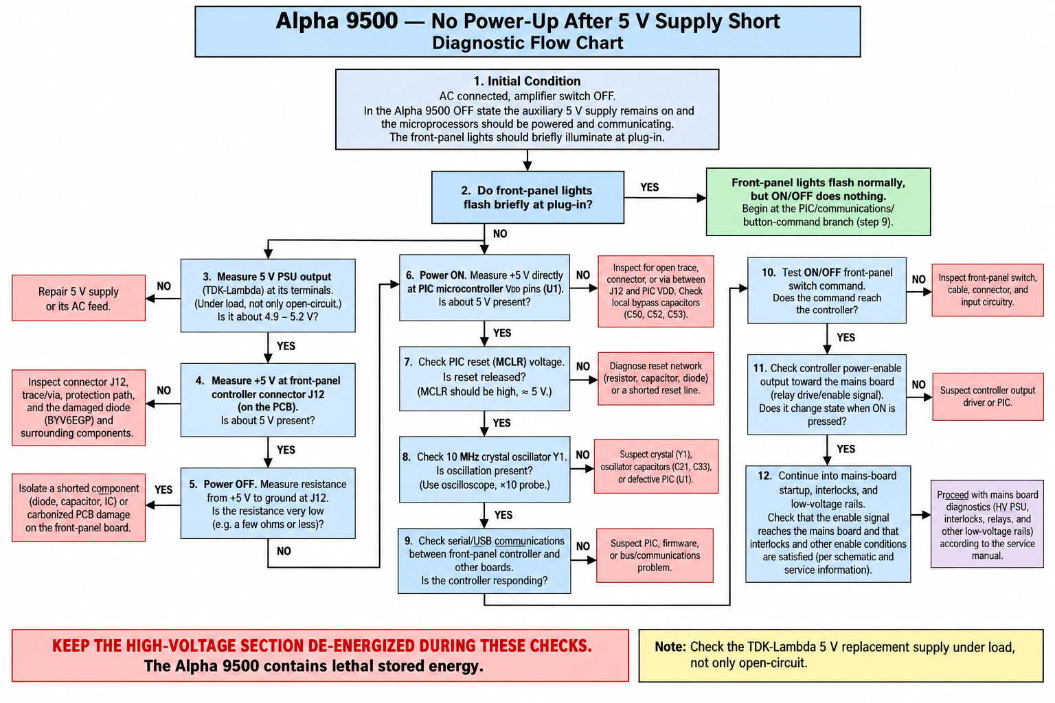
Diagnostic flow chart
Follow the sequence from the top. Do not jump immediately to the HV power supply or RF deck. The objective is first to determine whether the fault is an open 5 V distribution path, an excessive load on the 5 V rail, a controller-startup fault, or a failure farther downstream in the power-enable chain.
Step-by-step bench procedure
1. Observe the normal plug-in behavior
With the amplifier assembled in a safe condition and the front-panel power controls not pressed, connect AC mains and observe the front panel. According to the Alpha manual, the front-panel LEDs normally blink or illuminate briefly when the unit is first plugged in. The amplifier then enters its OFF state while the internal auxiliary logic supply remains active.
If Fred sees that brief flash: the 5 V logic system is at least partly alive, and attention can move toward controller communications and the ON/OFF command path. If there is absolutely no flash: begin at the replacement supply and work toward the controller.
2. Verify the replacement 5 V supply under load
Measure the TDK-Lambda output at the supply terminals while it is connected to the amplifier. Do not rely solely on an unloaded reading. A damaged controller board can pull a supply into current limit while an open-circuit supply still measures a perfect 5 V.
| Measurement | What to look for | Interpretation |
|---|---|---|
| PSU output, unloaded | Approximately 5 V | Confirms the replacement supply can regulate without the amplifier load. |
| PSU output, connected | Should remain close to nominal | A collapse suggests excessive load, a shorted component, wiring error or current limiting. |
| 5 V at the controller-board input | Approximately the same as PSU output | A difference points to the connector, harness, protection path, PCB trace or via. |
3. Confirm that 5 V reaches the controller board itself
Measure the 5 V rail at the front-panel/controller board connector rather than only at the Lambda supply. Use the correct schematic for the exact controller revision installed in the amplifier; Alpha publishes both Rev A and Rev B controller documentation. If the supply is correct at its terminals but missing at the PCB, inspect the harness, connector pins, the damaged-diode area, copper traces and plated-through vias.
4. With power removed, check the 5 V rail for an abnormal load
Disconnect AC mains, allow the amplifier to discharge as required by the service procedure, and then measure resistance between the 5 V logic rail and logic ground. Do not interpret a single resistance value too literally because electrolytic capacitors charge from the meter and semiconductor junctions affect the reading. The useful observation is whether the rail behaves like a near-dead short and remains there.
If the resistance remains extremely low, isolate loads systematically. Likely victims of a screwdriver event include a protection diode, bypass capacitor, electrolytic capacitor, regulator/protection component, logic IC, copper trace or carbonized PCB material.
5. Inspect the exact arc site under magnification
A large spark can damage more than the visibly failed BYV6EGP. Inspect both sides of the PCB and the nearby harness with bright light and magnification. Look for copper craters, darkened laminate, lifted pads, cracked SMD parts, damaged vias, vaporized trace necks, solder beads and contamination. Carbonized fiberglass can become partially conductive and create a persistent leakage path.
6. Verify logic voltage at the processor supply pins
If the board input has 5 V, the next question is whether the controller’s processor and associated logic actually receive that voltage. Use the controller schematic revision that matches Fred’s board and verify the processor supply pins directly. If approximately 5 V is present at the board input but absent at the processor, suspect an open trace, via, connector path or localized component failure.
7. Check reset and oscillator conditions
A microcontroller with correct supply voltage can still appear completely dead if its reset input is being held active or its clock is not running. Check the reset network against the applicable schematic and confirm that reset releases after power is applied. If the controller uses the documented crystal oscillator on Fred’s board revision, inspect it with a high-impedance ×10 oscilloscope probe and avoid loading the oscillator excessively.
8. Use USB or RS-232 as a controller-alive test
Alpha states that the USB and RS-232 ports remain active in the normal OFF state. That makes communications unusually useful here. If the front panel remains dark but a computer can still communicate with the amplifier, the primary controller is probably alive and the fault may lie in the front-panel/display path or power-button input. If neither port responds, return to supply, reset, clock and inter-processor communications before proceeding farther downstream.
9. Check the ON/OFF command path
The Alpha 9500 has an intermediate ON1 state. Alpha describes the ON/OFF (ANT SEL) button as the control that brings up the metering, band and antenna-selection functions without applying tube heater or plate HV. If the microprocessors are alive but pressing ON/OFF does nothing, trace the button, cable/connector path and input circuitry into the controller before investigating the high-voltage section.
10. Only then follow the power-enable chain toward the mains board
If the 5 V system is healthy, the processors boot, communications work and the front-panel command reaches the controller, then check whether the controller changes its power-enable/relay-drive output when ON is requested. If it does, continue with the mains-board startup chain, interlocks and low-voltage rails using the Alpha schematics for the amplifier’s exact board revisions.
This is the point where the diagnosis changes from “damage caused by the 5 V short” to “why the rest of the amplifier is not accepting a valid startup command.” Do not make that transition until the logic subsystem has been proven.
Fred’s first four measurements
These four observations should divide the problem quickly into a power-distribution fault, an excessive-load fault or a powered-but-nonrunning controller fault.
| # | Measurement | Expected observation | Diagnostic value |
|---|---|---|---|
| 1 | Replacement 5 V PSU under load | Stable near nominal | Separates PSU trouble from downstream loading. |
| 2 | 5 V at controller-board input | Near the PSU voltage | Tests the harness, connector and PCB feed path. |
| 3 | 5 V at processor logic supply pins | Near nominal logic voltage | Proves the processor actually receives supply voltage. |
| 4 | Resistance from 5 V to ground with power removed | Should not behave as a persistent near-zero-ohm short | Screens for a second damaged component on the 5 V bus. |
Most likely fault areas after this kind of short
What not to do
- Do not repeatedly cycle power hoping the amplifier will recover. The original event produced enough fault current to create a visible arc and smoke.
- Do not assume that replacing the visibly failed diode repaired every affected node.
- Do not conclude that the controller processor is bad merely because the front panel is dark.
- Do not begin by servicing the plate HV supply when the symptom began with a documented 5 V logic-supply short.
- Do not defeat safety interlocks for convenience.
- Do not use a board revision schematic that does not match the actual amplifier.
Factory documentation and service resources
Alpha RF Systems publishes unusually useful documentation for the 9500, including the operating manual, fault information, controller-board schematics for more than one revision, HVPS schematics, AC-mains schematics, BOMs, firmware notes and remote-control documentation. Before probing a component or connector by designator, identify the board revision installed in the amplifier and use the matching schematic.
Service escalation
Dishtronix currently lists the Alpha 9500 among the Alpha products it supports. If the troubleshooting reaches a damaged microcontroller, firmware issue, multilayer-board fault, or a condition that requires live measurements around the mains or HV circuits, stopping and sending the unit to an experienced Alpha service facility is a rational next step.
A healthy 5 V reading at the replacement supply does not establish that the Alpha 9500 controller survived the short. The fastest path is to prove the 5 V rail under load, prove that it reaches the controller and processor, rule out an abnormal short on the rail, then verify reset/clock/communications and the ON/OFF command path. Only after those tests pass should troubleshooting move toward the mains-board startup chain.
References
- RKR Designs LLC, Alpha 9500 Linear Amplifier User Manual, Document Issue 1.2, June 2015. See §2.9 “Power Supply” and Table 5-1 “Operational states.”
- Alpha RF Systems, Alpha 9500 Autotune Legal Limit support page and associated 9500 documentation library, including Main Controller Rev A/Rev B, HVPS and AC Mains schematics.
- Dishtronix / TEN-TEC Support, supported-product listing showing Alpha 9500 service support.
Editorial note: This is a diagnostic aid, not a substitute for the Alpha service manual or safe high-voltage service practice.